PCB Header Current Rating: Why Temperature Rise Matters More Than the Datasheet Number
PCB Header Current Rating: Why Temperature Rise Matters More Than the Datasheet Number
A header that appears adequate on a bill of materials may still need a lower current in a crowded, enclosed PCB assembly. The purchasing question is not just whether the catalogue number exceeds the load; it is whether that number represents the same loaded contacts, conductors and thermal environment. A single energized position on a test fixture is not evidence for a bank of adjacent power and return contacts beside a hot component. Missing those conditions can lead to board rework, a larger connector or repeat testing late in development. This guide explains how to compare rating evidence with the application before treating a current figure as a release limit.
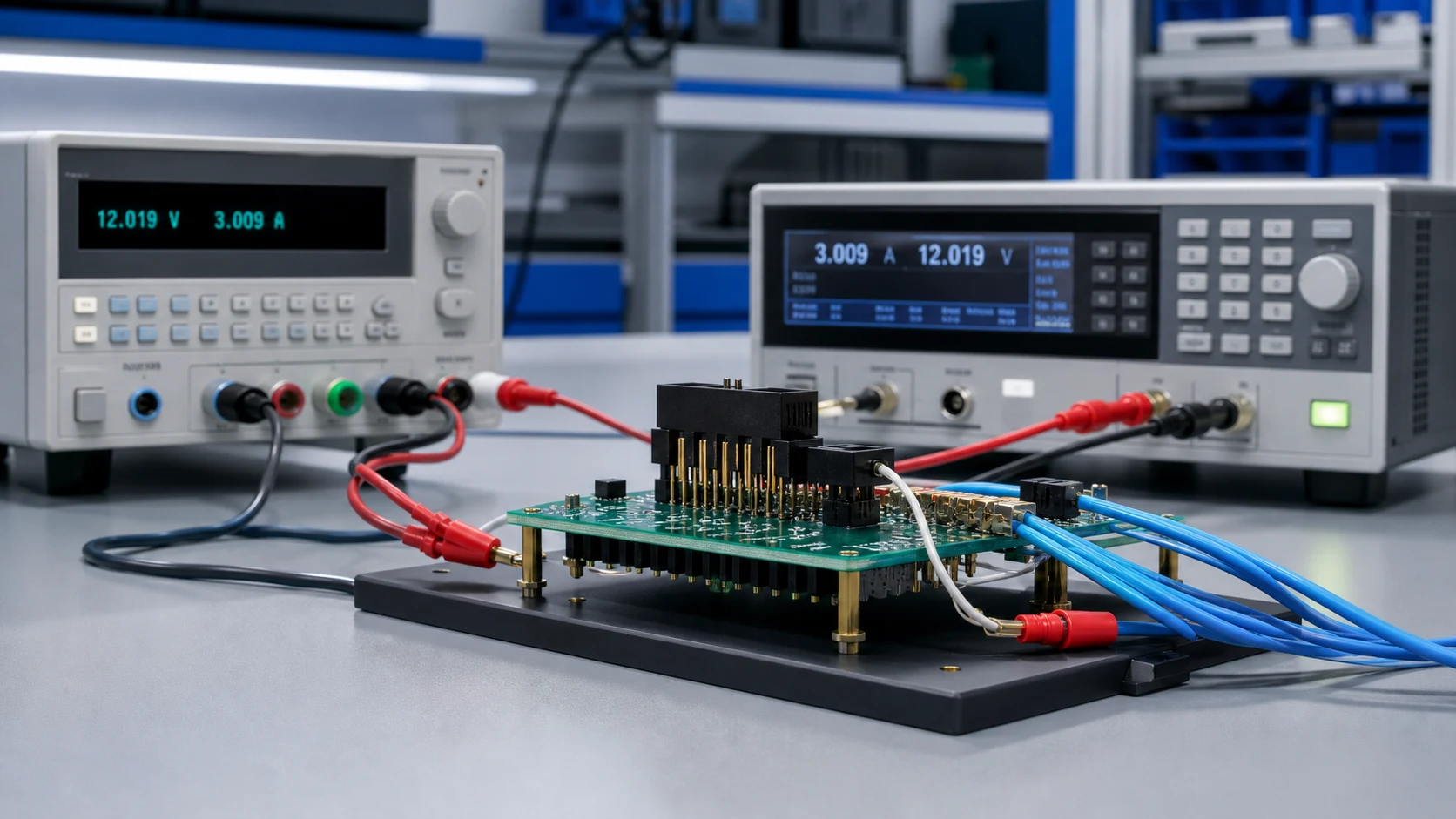
The short answer is that PCB header current rating must be evaluated against both permitted temperature rise and the applicable absolute temperature limits. Read the rating’s conditions, then verify the real contact grouping and ambient. IEC 60512-5-2:2002 addresses current-temperature derating at elevated ambient, but its public catalogue does not supply a universal reduction factor. For an enclosed product, verify the exact mated assembly on representative copper, with its actual load pattern and nearby heat sources. Accept it only against documented product limits and an agreed test plan; do not infer approval from pitch or a headline amperage alone.
Inhalt
A published current figure describes a specific test arrangement: a defined contact count under load, wire or trace sizes, ambient temperature and an allowed temperature rise. Change any of those conditions and the number no longer applies directly. If the catalogue does not disclose them, request the supporting specification or report rather than assuming an open-air, single-contact or all-contact test.
| Rating element |
What the catalogue states |
What your application changes |
| Loaded contacts |
Defined pattern in the test |
Real grouping and return paths |
| Conductors |
Test wire or trace sizes |
Actual trace cross-sections |
| Thermal context |
Declared ambient, airflow and rise limit |
Enclosure, stacking and local heating |
What should be compared before accepting the catalogue value?
Treat this as a test-condition comparison checklist, not a universal qualification standard. Record a match, difference or missing evidence for each item. An unexplained difference calls for supplier clarification or application testing; it does not justify an arbitrary percentage reduction.
- Exact header and mating part, contact finish, position count and document revision.
- Number and location of simultaneously loaded positions, current per position, return paths and continuous or cyclic duty.
- PCB copper thickness, trace width and length, pads, planes and vias; mating wire size and length where relevant.
- Local ambient definition, board orientation, enclosure, airflow, board spacing and neighbouring heat sources.
- Measurement points, thermal-stability criterion, sample condition, permitted rise, absolute temperature limits and decision margin.
The public description of IEC 60512-1:2018 explains that detail product specifications prescribe selected tests, severity and permissible performance limits. A reference to the IEC 60512 series therefore needs a product-specific acceptance specification; it is not certification of every installation.
How do temperature rise and absolute temperature differ?
Contact heating can contribute to relaxation, finish degradation and neighbouring component stress, depending on material, temperature and exposure. Interfaces are assessed against an agreed rise limit above a defined ambient, which helps explain why the same part can support different currents in different designs. That rise limit is only one acceptance condition.
Temperature rise is the difference between a measured point and its specified ambient reference. Absolute temperature is the actual temperature at that point. A small rise in an already hot enclosure can still exceed a component’s permissible temperature. Conversely, a cool ambient does not waive a separately specified rise limit. Check both criteria, and confirm whether the product’s operating-temperature range includes self-heating; a catalogue range alone does not answer that question.
For an illustrative calculation only, a measured point at 80 degrees Celsius and a defined ambient of 60 degrees Celsius give a rise of 20 kelvin. Neither number proves a pass: acceptance still depends on the applicable limits and where they must be measured. Housing, contact, PCB and adjacent-component limits may apply at different locations; one sensor reading cannot automatically represent them all.
Can current be scaled in proportion to temperature rise?
No. Resistive heating follows I-squared-R for a given resistance, so doubling current would quadruple dissipated power if resistance remained constant. Temperature rise is not simply power multiplied by a fixed factor in every assembly: resistance, heat transfer and neighbouring loads can change with temperature and operating conditions. Even a square-root estimate based on one measurement is only a screening approximation under restrictive assumptions, not a released rating.
Use a documented derating curve within its stated conditions or collect measurements across the relevant current and ambient range. IEC 60512-5-2:2002, Test 5b: Current-temperature derating assesses connector current-carrying capacity at elevated ambient. Its public summary establishes that scope, not a full procedure, fixed margin or linear conversion rule.
Contacts heat their neighbours, so a fully loaded header can run hotter than a single energized contact at the same per-contact current. Establish how many positions carry load simultaneously and how return paths are distributed before trusting any per-contact figure. The related PCB Header Pitch Selection: Matching Current, Density and Assembly Process guide covers spacing and density choices; the PCB Power Connector article provides broader selection context. Neither replaces the exact assembly’s thermal evidence.
Create a position-by-position load map rather than recording only total connector current. Identify adjacent power pins, loaded returns, unloaded signal positions and the combinations that can occur together. A return contact carrying several branch currents may be more heavily loaded than any one supply contact. Check realistic operating modes, including simultaneous loads and sustained duty; an evenly distributed test pattern is not interchangeable with a concentrated group of hot positions.
Parallel contacts do not automatically divide current equally. Differences in conductor length, termination resistance and interface resistance can produce unequal sharing. Multiplying a per-contact value by the number of parallel positions is not sufficient evidence. Verify current distribution and the hottest relevant points using the intended routing and mating assembly, including any credible imbalance required by the system’s acceptance plan.
Which board and enclosure conditions change usable current?
Elevated ambient, enclosed housings, small trace cross-sections, long duty cycles and stacked boards can reduce thermal headroom. List these factors explicitly in the design review so the derating logic is visible and repeatable. Higher ambient reduces the headroom to an absolute temperature ceiling; it does not necessarily change a separately specified permitted rise.
| Factor |
Direction of effect |
Review action |
| Higher ambient |
Less headroom to absolute temperature limits |
State worst-case local ambient |
| Full-position loading |
Potentially higher interface temperature |
Test the real load pattern |
| Thin traces |
Potential extra heating at pads |
Align layout with duty |
The board is part of the thermal system, not merely a fixture holding the header. Traces generate heat and copper can spread heat away from a termination; pads, planes and vias influence both effects. Record the actual copper geometry and the mating conductor arrangement. A generous laboratory coupon may behave differently from narrow production traces, and a wire-terminated mating connector adds its own thermal path. The limiting point may be a trace, termination or neighbouring component rather than the nominal header contact.
Run the representative assembly with the cover, board stack, fan state and orientation relevant to its intended use. Include normal concurrent heat sources instead of testing the connector in isolation and calling the result a system limit. If reduced airflow is an operating condition that the product must tolerate, assess it under the approved system plan. Do not assume a bench fan or open lid represents that condition.
How should the assembled product be tested?
Test the real footprint, trace layout, loaded positions and enclosure condition, and measure at the agreed points until readings stabilise. Define pass limits, instruments and records with the acceptance owner before the test starts. A useful PCB header current rating assessment separates a supplier’s component test from the application’s verification rather than presenting them as the same result.
- Freeze the sample configuration: header, mate, finish, PCB revision, assembly process and conductors. Record whether samples are new or conditioned.
- Apply the agreed simultaneous load map and current duty at the relevant local ambient, with representative board and enclosure conditions.
- Measure agreed contact, termination, housing or board points and the defined ambient reference. Record instrument calibration, placement and measurement uncertainty.
- Use a defined thermal-stability criterion for continuous loading. For cyclic or peak duty, also capture the relevant transient temperatures; a single settled reading cannot describe every duty profile.
- Compare every required reading against its rise and absolute temperature limits, retain the margins and obtain the designated acceptance decision.
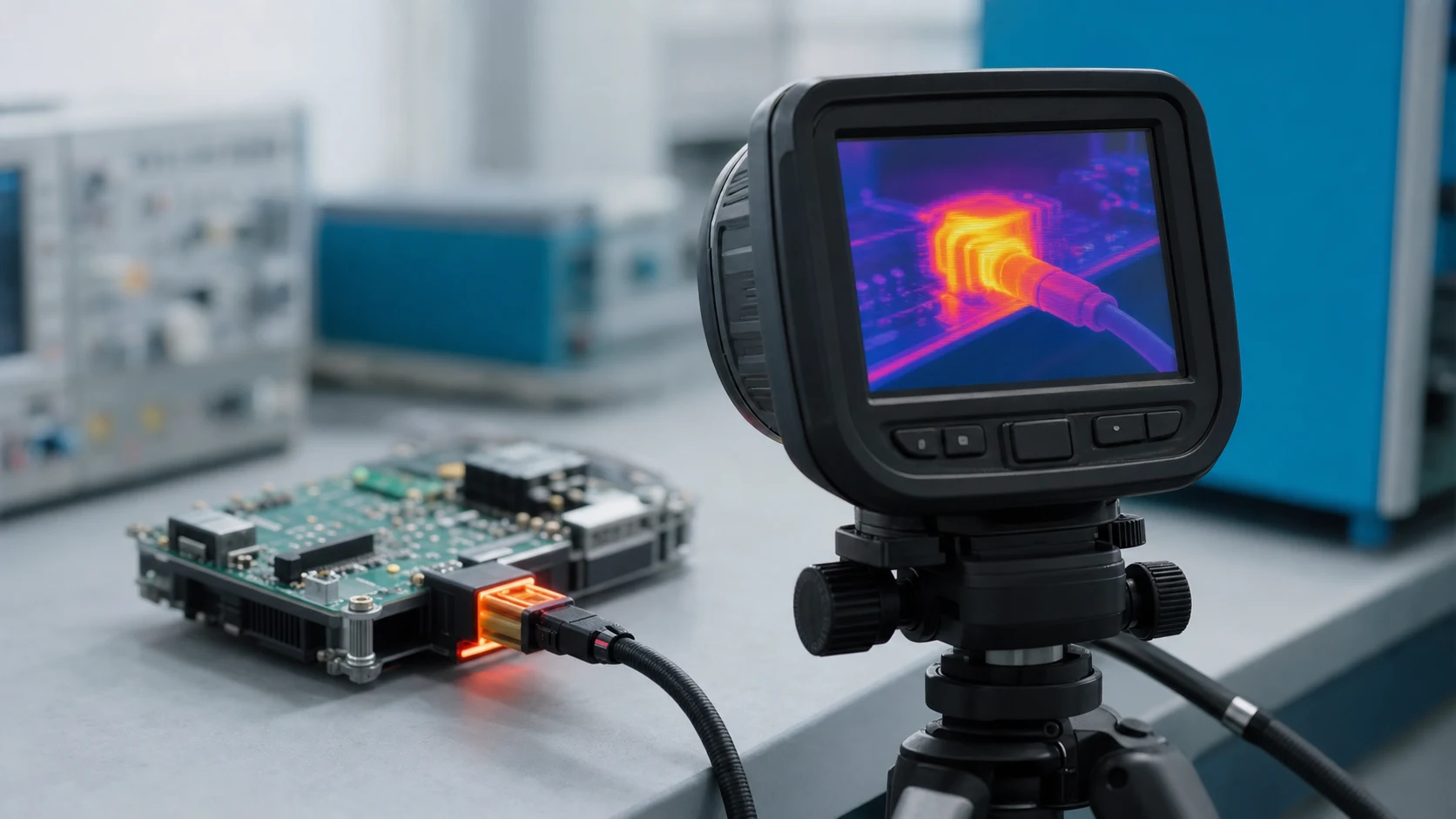
Thermal imaging can locate accessible hot areas, but a visible housing surface is not automatically the contact interface temperature. Reflective surfaces, emissivity assumptions and inaccessible measurement locations can affect interpretation. Agree a measurement method suitable for the required points; do not turn a colour image alone into a pass record.
Wichtig: General guidance cannot approve a specific design or lot. The IEC references below establish test scope and the role of product specifications, not the complete normative procedure or your acceptance limits. Apply the selected method through controlled product documentation and an approved application test plan.
What evidence and retest triggers belong in the release file?
Keep the rating’s stated conditions, your application assumptions, the rise measurements and the approved margins together. That file lets a later current increase or layout change be re-checked quickly instead of re-argued. Include the position load map, assembly drawing revisions, sensor locations, temperature-versus-time records, ambient reference and disposition of differences from the supplier’s setup.
A useful documentation example is TE Connectivity contact 2415838-1: its official page separately lists a current rating, product drawing 2415838 Rev A, application specification 114-106638 Rev B and product specification 108-106638 Rev A. This is a crimp receptacle contact terminating to wire and cable, not a PCB header. The example shows the documents to request; it establishes no ZUCH rating, mating compatibility or application approval.
Which changes require a thermal review or retest?
- Increased current, longer on-time, different simultaneous loads or reassigned supply and return positions.
- Changed copper thickness, trace geometry, pad/via arrangement, board stack or mating wire size.
- Changed enclosure, airflow, orientation, ambient specification or nearby heat-generating components.
- Changed header or mate, contact finish, termination process or supplier specification revision affecting the qualified configuration.
- Unexpected temperature drift, resistance change or visible damage that calls the previous acceptance evidence into question.
Use change control to decide whether existing evidence covers the change or a targeted retest is needed; do not transfer the old approval without review. Where environmental conditioning is part of the product specification, IEC 60512-11-1:2019, Test 11a: Climatic sequence addresses temperature, humidity and, where required, low air pressure. Its scope does not establish service lifetime or resistance to every chemical. Define any post-conditioning thermal or electrical checks in the qualification plan instead of claiming a new-sample rise test proves lifetime performance.
What should a current-rating inquiry to ZUCH include?
Use ZUCH’s PCB Header category and the live product catalogue to identify relevant connector, terminal or housing component families. These are discovery routes only and do not demonstrate that a specific configuration is approved for your application.
Which RFQ inputs make the rating assessable?
- Electrical duty per contact, load pattern and worst-case local ambient, including relevant peak or cyclic conditions.
- Board layout context: traces, copper thickness, vias, stacking and enclosure condition; identify the intended mate.
- Agreed temperature-rise limit, applicable absolute temperature limits, selected test method and acceptance records.
- Samples and controlled documentation needed for the release file, with open questions about the supplier’s rating setup.
Where does this guidance stop?
This guide supports engineering and sourcing discussion; it cannot replace programme-specific validation, market requirements, or an approval record. Use ZUCH’s sample request route or contact page for controlled component documentation and samples.

FAQ
What does the current rating on a PCB header mean?
It reports a current capability under defined conditions; it is an input, not an application approval. Request the specified load pattern, conductors, ambient and acceptance limits before applying the value to a different assembly.
Why do two designs get different usable currents from one header?
Grouping, traces, ambient and enclosure differ, so each design can reach its thermal limits at a different current. Compare the complete mated configuration, not just the shared header part number.
What is a temperature-rise check?
It measures the temperature difference between specified points and a defined ambient reference under an agreed load and setup. Check absolute temperatures as well: meeting a rise criterion alone does not prove compliance with a component’s maximum temperature.
Do all contacts in a header share current equally?
Not automatically. Path resistance and layout influence sharing, so parallel-contact schemes need their own review and measurements. Do not multiply the single-contact rating by the number of parallel positions without supporting evidence.
When should derating be applied?
Review usable current whenever application conditions differ from the rating setup, especially at elevated local ambient or with concentrated loading. Use a relevant documented curve or application data; there is no universal percentage established by the public IEC catalogue summary.
Can plating choice change thermal behaviour?
Contact finish can influence interface behaviour, so confirm that the specified finish matches the rated and tested configuration. Finish names alone do not establish higher usable current or longer life. Treat a finish substitution as a controlled change requiring evidence review.
What should buyers request in a current-rating RFQ?
Request rating conditions, relevant drawing and specification revisions, supporting test context, and samples for an application check. Supply the position load map and board/enclosure details so that an answer refers to the intended assembly rather than an unspecified catalogue condition.
References
Public source descriptions checked on 10 October 2026. The IEC catalogue summaries verify scope, not full normative procedures or numerical acceptance limits.
When is a header current ready for release?
A defensible PCB header current rating decision connects a catalogue value to a documented assembly, rather than choosing a convenient margin and assuming the conditions match. First identify the exact header and mate, the simultaneous load map and the local thermal environment. Then compare supplier evidence with the real copper, enclosure and duty profile, and verify both temperature rise and absolute temperature at the required points. Do not skip application testing where the available evidence cannot cover a meaningful difference, and do not extend one measurement by linear extrapolation. Keep the accepted configuration and change-review triggers in the release file. ZUCH’s product and sample routes provide a starting point for component selection and documentation requests; submit the same board and load information through the contact route so the inquiry has an assessable technical boundary.
 Zhejiang ZUCH Technology Co., Ltd.