Zhejiang ZUCH Technology Co., Ltd.
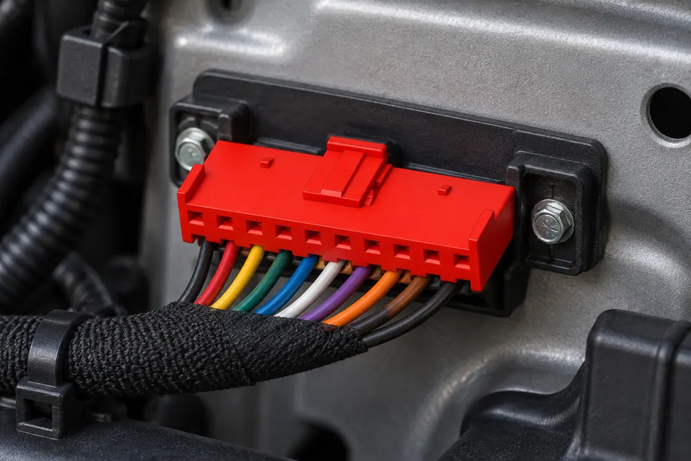
When a harness designer in Detroit matched a ten-circuit lighting connector, two housings looked identical but keying and terminal sizes caused a no-start test failure; the root cause was fitment verification, not a defective connector.
Zusammenfassung: A 10-pin automotive connector is a ten-position interconnect, not a universal part number. Confirm the mating housing, keying, cavity layout, terminal family, wire range, current and voltage, sealing level, and service requirements before release to production. As a practical distinction, a connector can have ten cavities while only some carry load current; size each terminal and circuit individually, then validate the assembly with the applicable OEM procedure and connector-system tests such as those described in SAE USCAR-2. The recommended action is to approve a drawing and sample pair—not a photograph—before purchasing volume.
In automotive lighting, body controls, sensors, and small modules, ten circuits can combine power, ground, signal, and communication functions. That combination makes a compact housing attractive, but it also increases the consequence of one misplaced terminal. The right specification therefore starts with the harness interface and operating environment, then narrows the connector family.
Why a 10-pin label is not enough to confirm compatibility
How to map populated cavities, spare cavities, and mating direction
Map every circuit that the harness must carry. Record nominal voltage, continuous and inrush current, signal type, duty cycle, wire insulation, and the required cavity position. A lighting assembly may use one or two higher-current feeds alongside low-current control lines; a single “10-pin” label does not tell you whether all ten positions use the same terminal or wire gauge.
Check the mating connector’s manufacturer, family, part number, gender, keying, latch location, and terminal orientation. Compare a controlled drawing or 3D model with the vehicle-side component. SAE USCAR-2 treats connector performance as a system attribute—housing, terminals, seals, and retention—so visual similarity alone is not evidence of interchangeability.
| Fitment checkpoint | What to verify | Why it matters in production |
|---|---|---|
| Position and cavity map | Pin numbers, view orientation, populated and spare cavities | Prevents reversed feeds, open circuits, and no-start faults |
| Keying and latch | Key code, polarization ribs, CPA/TPA and mating direction | Stops a look-alike housing from mating incorrectly or backing out |
| Terminal system | Contact family, plating, crimp barrel and approved wire range | Controls contact resistance, pull-out strength, and crimp quality |
| Envelope | Panel cutout, clearance, cable exit, bend radius and strain relief | Avoids interference and harness stress during vehicle assembly |
Ask for a first-article fit check using both halves of the intended interface. Confirm that the latch reaches its locked position and that the secondary lock cannot be closed over a partially seated terminal. A continuity check should follow mechanical fitment; continuity by itself cannot prove correct keying or retention.
How to size terminals and wires for the real circuit mix
Terminal selection is a current-density and connection-quality decision. Match each circuit to the terminal’s approved wire range and current rating at the expected temperature, bundling, and duty cycle. Copper-alloy contacts with tin, nickel, or gold finishes may be available, but the finish must suit the mating system and environment; do not mix families because the dimensions appear close.
Use the connector supplier’s crimp specification and a controlled crimp-height or pull-test method. IEC 61984 provides a useful safety framework for connector design and testing, but it does not replace the terminal maker’s application specification. For a broader explanation of contact and housing choices, see the automotive connectors and terminals guide.
| Application dimension | Lower-demand example | Higher-demand example | Selection implication |
|---|---|---|---|
| Signal or sensor circuit | Low current, thin wire, stable environment | Low-level data or noise-sensitive input | Prioritize contact stability, plating, and routing; verify impedance and shielding needs |
| Lighting or actuator feed | Moderate continuous load | Inrush or sustained higher current | Check terminal size, temperature rise, fuse strategy, and adjacent-cavity derating |
| Harness environment | Cabin or protected module | Engine bay, splash, salt, vibration | Specify seal, CPA, strain relief, and validation tests for the actual location |
| Service expectation | Factory-only assembly | Field repair or repinning | Confirm replacement terminals, seals, tools, and inspection criteria are available |
Use the 10-pin count as a packaging constraint, then let electrical load determine terminal mix. If all circuits cannot share one contact size, select a mixed-terminal family only when the housing and tooling explicitly support it. This approach reduces hidden cost from oversized terminals, duplicate housings, rework, and field returns.
How sealing, keying, TPA, and CPA reduce field-failure risk
Sealed and unsealed versions can share an outline while having different grommets, cavity plugs, and validation requirements. For an engine-bay or exterior connector, define water, dust, salt, temperature, vibration, and chemical exposure before choosing the seal. A waterproof claim should identify the test condition and assembly state; it should not be inferred from a rubber insert alone.
The waterproof connector guide explains why ingress protection depends on the complete mated system. Confirm that unused cavities are plugged, wires are within the seal’s diameter range, and the cable exit is supported. IEC 61984 and the vehicle maker’s validation plan can inform test selection, while the destination market and end-use determine any additional regulatory evidence.
Mechanical protection also includes polarization, terminal-position assurance, connector position assurance, and a latch that can tolerate the specified vibration profile. A connector that survives a bench insertion may still fail a vibration or thermal-cycle test if the harness is unsupported. Build the retention and strain-relief checks into design verification rather than treating them as incoming inspection only.
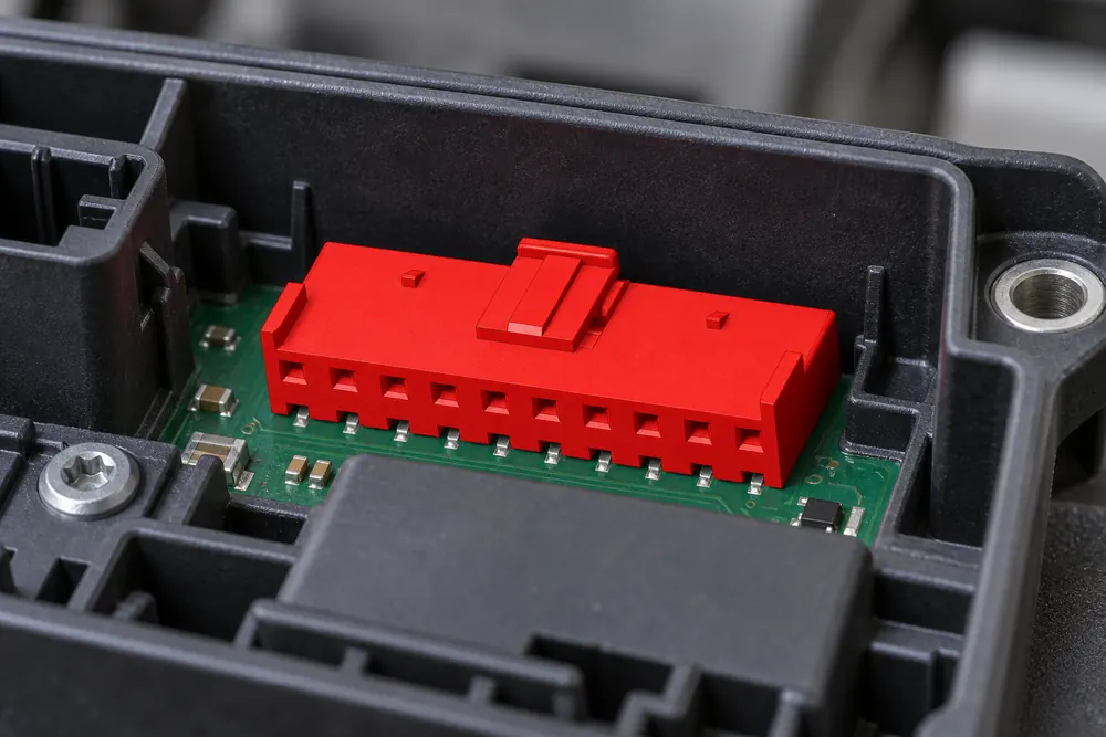
What evidence should purchasing request before approving a 10-pin connector sample?
Request a controlled datasheet, dimensional drawing, terminal and seal part numbers, material declarations, and a change-notification process. SAE USCAR-2 is a performance specification and test reference for automotive connector systems; it is not, by itself, a blanket certification for every assembled harness. IEC 61984 addresses safety requirements and tests for connectors, with applicability depending on the product and market.
For US vehicle applications, NHTSA’s vehicle-safety resources provide regulatory context, but NHTSA does not certify every connector. Determine what evidence the vehicle OEM, destination market, and customer quality system actually require. Unsupported claims about waterproofing, temperature range, or certification can create warranty, recall, and sourcing risk even when the part appears mechanically acceptable.
Evaluate total cost of ownership, not unit price alone. Include terminals and seals, applicators, crimp validation, testing time, repair kits, minimum order quantities, engineering changes, and the cost of a mis-mated harness. A short sample-and-approval cycle is usually cheaper than correcting a tooling or wiring error after launch.
What should you send a supplier before releasing a 10-pin connector?
- Freeze the interface: capture vehicle-side part number, mating half, key code, cavity view, and envelope.
- Build the circuit matrix: list current, voltage, wire gauge, signal type, temperature, and duty cycle for each of the ten positions.
- Screen environment and service: select sealing, CPA/TPA, strain relief, and whether terminals must be field-replaceable.
- Approve evidence: review drawings, material and test data, crimp instructions, samples, and change-control terms.
- Run validation: perform fit, mating-cycle, retention, continuity, crimp, thermal, vibration, and ingress tests required by the application.
ZUCH can support buyers who need a configurable 10 pin automotive connector with documented terminal, housing, and sealing options. Share the vehicle interface, circuit matrix, environment, annual volume, and required evidence so the recommendation is based on fitment and validation—not a stock image or a pin-count shortcut.
Frequently asked questions
What is a 10-pin automotive connector typically used for in multi-wire lighting and control circuits?
It links up to ten circuits between a harness and a lamp, body-control module, sensor assembly, or actuator. The positions may carry a mix of power, ground, dimming, feedback, and communication signals. Confirm the actual pinout and current per cavity because “10-pin” describes positions, not a standard circuit assignment.
How do I confirm that a 10-pin automotive connector matches my vehicle wiring?
Match the vehicle-side part number, housing family, keying, cavity numbering view, terminal type, and wire range against an approved drawing or OEM service document. Then test a sample mating pair for latch engagement, terminal seating, continuity, and required environmental performance. A similar silhouette or shared pin count is not sufficient.
Do 10-pin automotive connectors need a matching male and female housing?
Yes, a mated system requires the specified plug and receptacle (or equivalent board/header interface) with compatible terminals and locks. Gender terminology can vary by connector family, so use the manufacturer’s part numbers and mating tables. Never assume that two ten-position housings from different families will mate safely.
What terminal and wire-gauge options are common for a 10-pin automotive connector?
Options commonly span small signal contacts and larger power contacts, with wire ranges defined by the terminal family rather than by the housing count. Tin-plated copper-alloy contacts are common; other finishes may be specified for corrosion or low-level signal needs. Select each cavity from the approved crimp, current, temperature, and sealing data.
When should I choose a sealed 10-pin automotive connector?
Choose a sealed version when the mated interface sees splash, dust, salt, condensation, or engine-bay exposure, and validate the complete assembly. Make sure wire diameter, cavity plugs, backshell, and strain relief match the seal system. For protected cabin locations, an unsealed design may reduce cost and service complexity if the vehicle specification permits it.
Can I replace one terminal in a 10-pin connector without replacing the full housing?
Sometimes, if the housing is serviceable and the terminal, seal, and extraction tool are approved for replacement. Inspect the cavity, locking lance, secondary lock, wire crimp, and seal after removal; damage or loss of retention requires replacement of the affected parts. Follow the connector maker’s service procedure rather than forcing a generic terminal into the cavity.
Sources for 10-pin connector selection and validation
- SAE USCAR-2: Performance Specification for Automotive Electrical Connector Systems
- IEC 61984: Connectors — Safety requirements and tests
- National Highway Traffic Safety Administration: Vehicle Safety
The durable rule is simple: count the circuits, but approve the whole interface—keying, terminals, seals, tests, and service plan—before the first production harness is built.
For a documented 10 pin connector automotive solution, review the ZUCH connector products and contact the team with your pinout, mating part, environment, and validation requirements.