Zhejiang ZUCH Technology Co., Ltd.
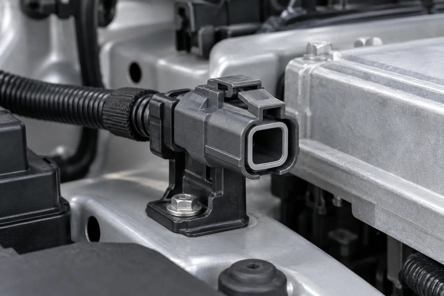
When a vehicle service engineer in Melbourne encountered an intermittent cooling-fan feed, he replaced its damaged single-circuit plug with a visually similar unit. During the first loaded test, the replacement overheated and the insulation began to soften. The failure did not show that one-pin connectors are inherently defective: the terminal, wire size and seal were mismatched rather than verified as one compatible system.
Zusammenfassung: Use a 1 pin automotive connector when one separable circuit—power, ground or signal—needs a keyed, retained interface. Do not select by cavity count or appearance alone. Confirm the mating housing, terminal series, conductor cross-section, insulation diameter, current and environmental exposure; then validate the assembled connection in the relevant SAE/USCAR-2 or ISO 8092 test context. Even an illustrative 10 mΩ connection at 20 A dissipates 4 W through I²R, so a small compatibility error can become a costly heat source.
What Problem Does a One-Circuit Connector Solve?
A one-pin connector carries one electrical path through one terminal position. It suits a solenoid feed, switch output, warning-lamp lead, sensor line or isolated ground return. The circuit still needs a return elsewhere, so map the conductor from source to load before ordering.
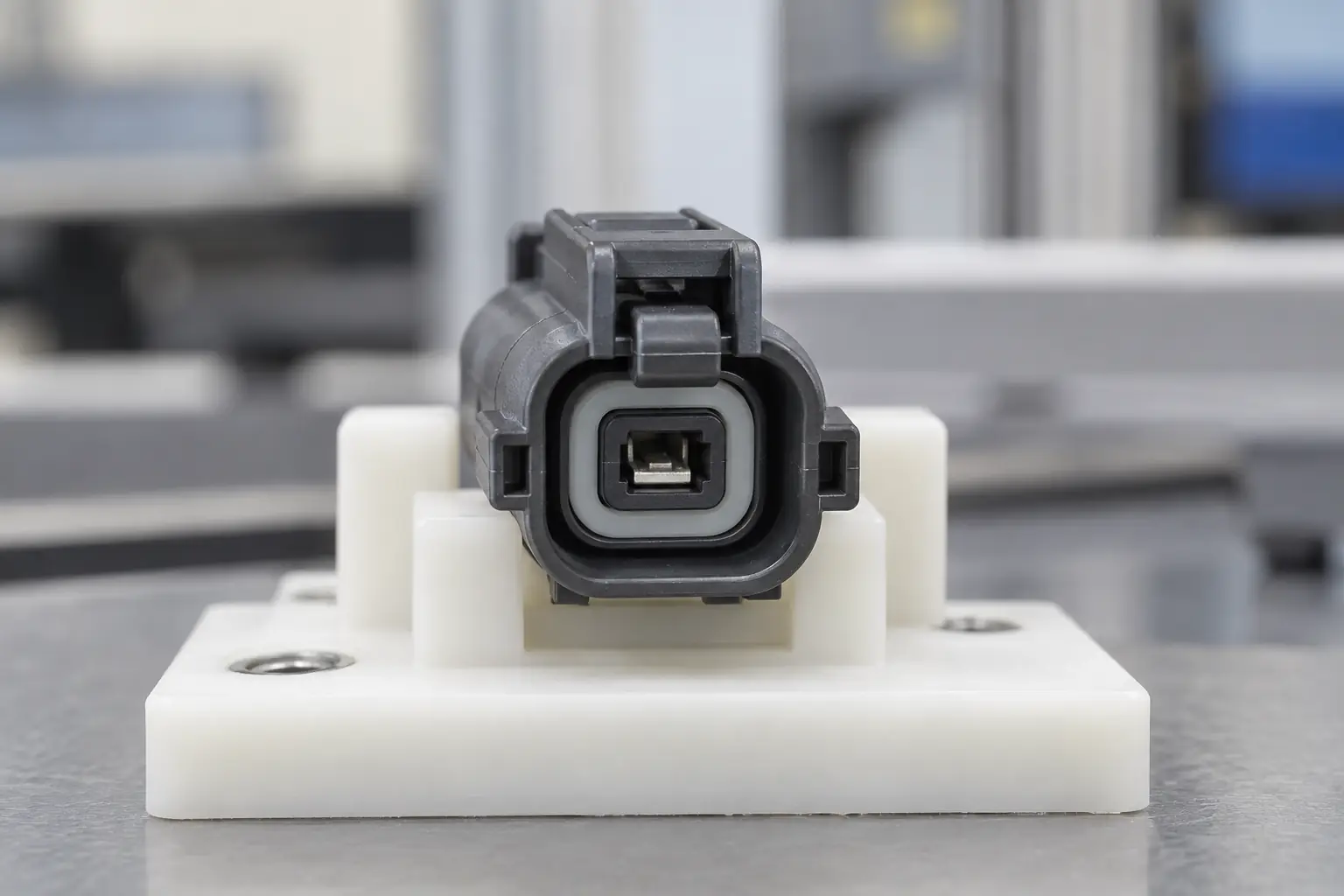
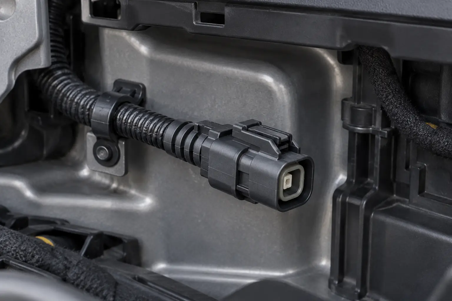
The principal benefit is serviceability. A keyed housing locates the contact, a latch maintains the interface, and optional seals manage exposure. A 1 pin automotive connector is therefore a system of mating sides, compatible contacts, any required seals and correctly prepared conductors—not merely a plastic shell.
Choose One Pin Only When One Separable Conductor Is Enough
Which Power, Ground and Signal Duties Suit One Position?
Choose one position when the branch has one separable path and independent servicing has value. Avoid splitting several related circuits among one-pin housings when a keyed multi-pin connector would reduce assembly time and cross-connection risk.
Current capability depends on contact design, wire size, crimp quality, temperature, duty cycle and derating. Illustratively, a 10 mΩ interface produces 1 W at 10 A but 4 W at 20 A because heating rises with current squared. Loaded voltage-drop and temperature-rise checks should therefore complement SAE/USCAR-2-style resistance and environmental sequences.
The Cheapest Housing Can Create the Highest Service Cost
The lowest-price housing becomes expensive if it needs unusual tooling, permits terminal back-out or cannot be serviced consistently. Compare the complete mated set, terminals, seals, tooling, inspection, spares and documentation. Rework, diagnostics and downtime can outweigh a small component-price difference.
Use Two Pins When the Return Path Needs Its Own Controlled Conductor
A one-pin device may complete its circuit through its metal body, the engine or the chassis. This architecture can be appropriate when the original design intentionally uses a bonded return and validation confirms reliable service. One visible wire does not mean the electrical function has no second side: current must return to its source, and the circuit reference must be defined.
Prefer a two-pin feed-and-return connection when the mounting path can vary. Paint, sealant, corrosion, a loose fastener, dissimilar metals or a repair change can add resistance or intermittency at engine and chassis joints. On a low-level analog sensor, a shifting ground reference can reduce sensor accuracy relative to the control module; on a diagnosed load, it can undermine diagnostic stability. A dedicated return places both conductors within the controlled connector-and-harness system and makes faults easier to isolate.
Load current and polarity also matter. A chassis return that passes a continuity check can still develop voltage drop or heat under load, while a shared-return drop can disturb other circuits. A two-pin interface can carry an assigned supply and return and preserve required polarity. Both contacts, wires and seals still need selection for actual load and fault conditions; there is no universal current threshold for choosing one or two pins.
Compact decision rule: use one pin when the documented circuit intentionally completes through a validated body, engine or separate return and testing confirms a stable reference. Use two pins when return integrity, sensor accuracy, diagnostic repeatability, polarity control or service isolation should remain inside the harness.
Verify the choice against the wiring diagram and device drawing. De-energized continuity can screen for an open path, but also measure voltage drop from the device return to its reference under representative load and inspect the ground joints. Acceptance limits must come from the OEM or customer specification and validation plan, not from connector cavity count.
Terminal, Seal and Retention Compatibility Determines Reliability
In an open-barrel crimp, one wing set joins the conductor while another supports the insulation. Too little compression can raise resistance; too much can cut strands or deform the contact. Use the terminal supplier’s conductor range, strip length, crimp-height and pull-force criteria.
A wire seal has an insulation-diameter window and orientation. An oversized seal may tear; an undersized wire may leave a leak path. Sealing cannot compensate for a damaged cavity, poor routing or exposure beyond the validated conditions.
The crimp retains the wire in the terminal; the locking feature and any secondary lock retain the terminal in the housing. Check insertion with the specified push-pull verification and confirm the secondary lock position. Because a crimp pull test is normally destructive, use defined process-control samples rather than a finished repair unless the approved procedure states otherwise. Acceptance values come from the drawing, customer specification and validation plan—not from cavity count.
Verify Mating Geometry, Repairability and Performance Under Load
A visually similar plug may not mate correctly. Verify family, part number, keying, latch geometry, cavity orientation, terminal sex, contact size and plating. Because “male” and “female” may describe the housing or metal contact, rely on drawings and approved mate lists.
A damaged terminal can often be replaced if the cavity, latch, secondary lock and seal surfaces remain sound. De-energize the circuit, use the specified extraction tool and inspect the parts. Install a new compatible terminal and seal; do not reuse a damaged contact.
Test continuity only on a de-energized circuit. A multimeter beep confirms a path, not acceptable performance under load. Where milliohm-level contact resistance matters, a suitable four-wire measurement can remove test-lead resistance from the result; then run an approved loaded voltage-drop check and inspect for heat. High-voltage, airbag and other safety-related circuits require dedicated OEM procedures.
Which Connection Approach Best Fits the Circuit and Service Environment?
| Connection approach | Best fit | Compatibility and durability focus | Unit-cost tendency | Maintenance and TCO implication |
|---|---|---|---|---|
| Sealed one-pin connector | One exposed, serviceable circuit | Terminal, wire seal and interface seal must be one validated system | Higher than an unsealed equivalent | Can reduce contamination-related rework when exposure justifies sealing |
| Unsealed one-pin connector | Protected cabin or enclosure location | Retention, strain relief and temperature remain critical | Usually lower | Simple service, but unsuitable exposure can raise return risk |
| Multi-pin connector | Several related circuits at one interface | Pinout, keying and aggregate thermal loading require control | Higher per housing; potentially lower per circuit | Fewer mating actions, with broader impact if the housing is damaged |
| Permanent splice or ring terminal | Non-separable branch or stud ground | Splice sealing or stud torque and corrosion control | Often low | May improve simplicity but reduce modular serviceability |
Match the One-Pin System to the Application and Validation Plan
| Application | Electrical duty | Dimensions to verify | Priority validation |
|---|---|---|---|
| Sensor or switch lead | Low-current signal | Contact finish, conductor area, keying, circuit sensitivity | Contact stability, vibration and intermittent-event monitoring |
| Solenoid or relay-coil feed | Inductive load | Steady current, inrush, suppression strategy, temperature | Loaded voltage drop, thermal rise and cycling |
| Lamp or auxiliary load | Power feed | Operating current, duty cycle, wire size, derating | Temperature rise and resistance after environmental conditioning |
| Ground jumper | Return path | Fault-current path, mounting architecture, corrosion exposure | Voltage drop and comparison with a sealed splice or ring terminal |
| Exterior single circuit | Signal or power | Insulation diameter, seal range, routing and splash zone | Water exposure, thermal cycling, vibration and retention |
Standards Define the Test Context—Not Universal Product Certification
- SAE/USCAR-2: a performance specification for automotive electrical connector systems. Its procedures address electrical, mechanical and environmental performance in defined categories. A statement that a design uses USCAR-2 methods is not, by itself, proof that every part number, crimp and vehicle application passed an OEM validation programme.
- ISO 8092-2:2005: road-vehicle context for definitions, test methods and general performance requirements for on-board electrical wiring-harness connections. Buyers should confirm the applicable ISO part, edition and customer requirement for the intended vehicle programme.
- IEC 61984:2008: safety requirements and tests for connectors above 50 V and up to 1,000 V AC/DC, with rated currents up to 125 A per contact; for connectors up to 50 V it may be used as a guide. It is not a vehicle-specific substitute for harness and OEM requirements.
These are standards or test frameworks, not universal product certifications. Vague claims invite rejected samples, repeated validation and field returns. State the destination market, vehicle zone, circuit duty, test sequence, limits and evidence package on the request for quotation.
Select the Complete One-Pin System in Five Evidence-Based Steps
- Define the circuit. Record normal current, inrush or fault conditions, voltage, duty cycle and allowable voltage drop.
- Define the environment. Specify temperature, vibration, fluids, splash or immersion exposure, mounting and service cycles.
- Control the complete mate. Use drawings to confirm male/female housing compatibility, terminal series, seal range, keying and secondary retention. The guide to identifying automotive electrical connectors offers a practical inspection sequence.
- Control the process. Approve the wire, strip length, tooling, crimp criteria and inspection record. Review this guide to crimping automotive connectors before setting work instructions.
- Validate representative assemblies. Test production-equivalent terminals, wires, seals and tooling against the agreed electrical, mechanical and environmental plan.
ZUCH supports connector and terminal selection for automotive and electrical applications. When requesting a 1 pin automotive connector, provide the mating-side information, wire and insulation dimensions, circuit load, environment and required evidence so the selection can be checked as a system rather than by appearance.
Frequently Asked Questions
What is a 1-pin automotive connector typically used for in single-circuit power, ground or signal wiring?
It provides a separable interface for one power feed, ground return or signal path, such as a switch lead, actuator feed or warning-lamp circuit. Confirm current, environment and where the return is made; one pin does not form a complete two-wire loop.
How do I confirm that a 1-pin automotive connector matches my vehicle wiring?
Match the housing and mate, keying, terminal size and sex, conductor cross-section, insulation diameter, seal range and circuit conditions. Use drawings, vehicle wiring information and an approved mate list—not photographs alone. Also compare automotive wire connector types.
Do 1-pin automotive connectors need a matching male and female housing?
Usually: an inline connection requires compatible mating sides and contacts. A receptacle that mates directly to a device header may need only the harness-side housing, but the device interface still defines the mate. Housing and terminal gender are not interchangeable terms.
What terminal and wire-gauge options are common for a 1-pin automotive connector?
Open-barrel pin, tab and receptacle contacts are common. Catalogues often group 0.35–0.5 mm² for smaller signals, 0.75–1.5 mm² for general circuits, and 2.0–2.5 mm² or larger for power, but these are selection bands—not ratings. Verify the terminal drawing, insulation diameter, current, temperature and tooling.
When should I choose a sealed 1-pin automotive connector?
Choose sealing for locations exposed to splash, road spray, dust, condensation or fluids when the validation plan requires it. Match the seal to insulation diameter. Sealing may be unnecessary in protected interiors and cannot replace correct routing or strain relief.
Can I replace one terminal in a 1-pin connector without replacing the full housing?
Often yes, if the cavity, latch, secondary lock and sealing surfaces pass inspection and approved repair parts are available. Replace a heat-damaged, cracked or non-retaining housing. Follow the safe sequence for depinning an automotive connector, then verify retention, continuity and loaded voltage drop.
Which Sources Support These Selection and Test Principles?
- SAE International, USCAR-2: Performance Specification for Automotive Electrical Connector Systems
- ISO 8092-2:2005, Road vehicles—Connections for on-board electrical wiring harnesses—Part 2
- IEC 61984:2008, Connectors—Safety requirements and tests
- Fluke, A Guide to Continuity Testing with a Multimeter
The durable decision is not “one pin or many”; it is whether every part of the connection is compatible, controlled and validated for the real circuit.
For sourcing support, review the ZUCH product range and contact the team with your wire dimensions, mating-interface details, electrical load and validation requirements.