Zhejiang ZUCH Technology Co., Ltd.
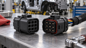
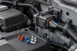
When a harness engineer in Detroit sees an eight-cavity plug fit the vehicle-side outline but the latch will not close, the temptation is to blame a defective part. The faster diagnosis is usually selection: the keying, terminal family, cavity view, or wire range does not match the specified interface. That mismatch can create an open circuit, a backed-out terminal, a difficult assembly, or a return after the vehicle leaves the line. This guide sets out a practical way to choose an eight-position connector for lighting, sensors, accessory harnesses, and compact modules. It focuses on the evidence a buyer should request before approving samples: the mating drawing, circuit matrix, terminal and seal data, and application-specific validation.
Zusammenfassung: An 8 pin automotive connector is an eight-position housing and terminal system, not a universal pinout. Confirm the mating half, keying, cavity numbering, terminal family, wire range, current and voltage for each circuit, environment, and service plan before ordering. ISO 8092 addresses connections for on-board vehicle wiring harnesses, while SAE USCAR-2 provides a performance and test framework for automotive connector systems. The recommended next step is a drawing-led sample approval: mate the intended plug and receptacle, inspect terminal seating and secondary locks, then validate fit, retention, crimp quality, and environmental requirements for the vehicle location.
Eight circuits are common where one harness must carry a mix of power, ground, sensor signals, feedback, and accessory functions. The pin count helps package that mix, but it does not define contact size, polarity, sealing, or interchangeability. For an automotive 8 pin connector, a buyer who starts with the complete interface can compare suppliers on usable evidence rather than on a similar-looking photograph.
What does an 8-pin count tell you about a vehicle connector?
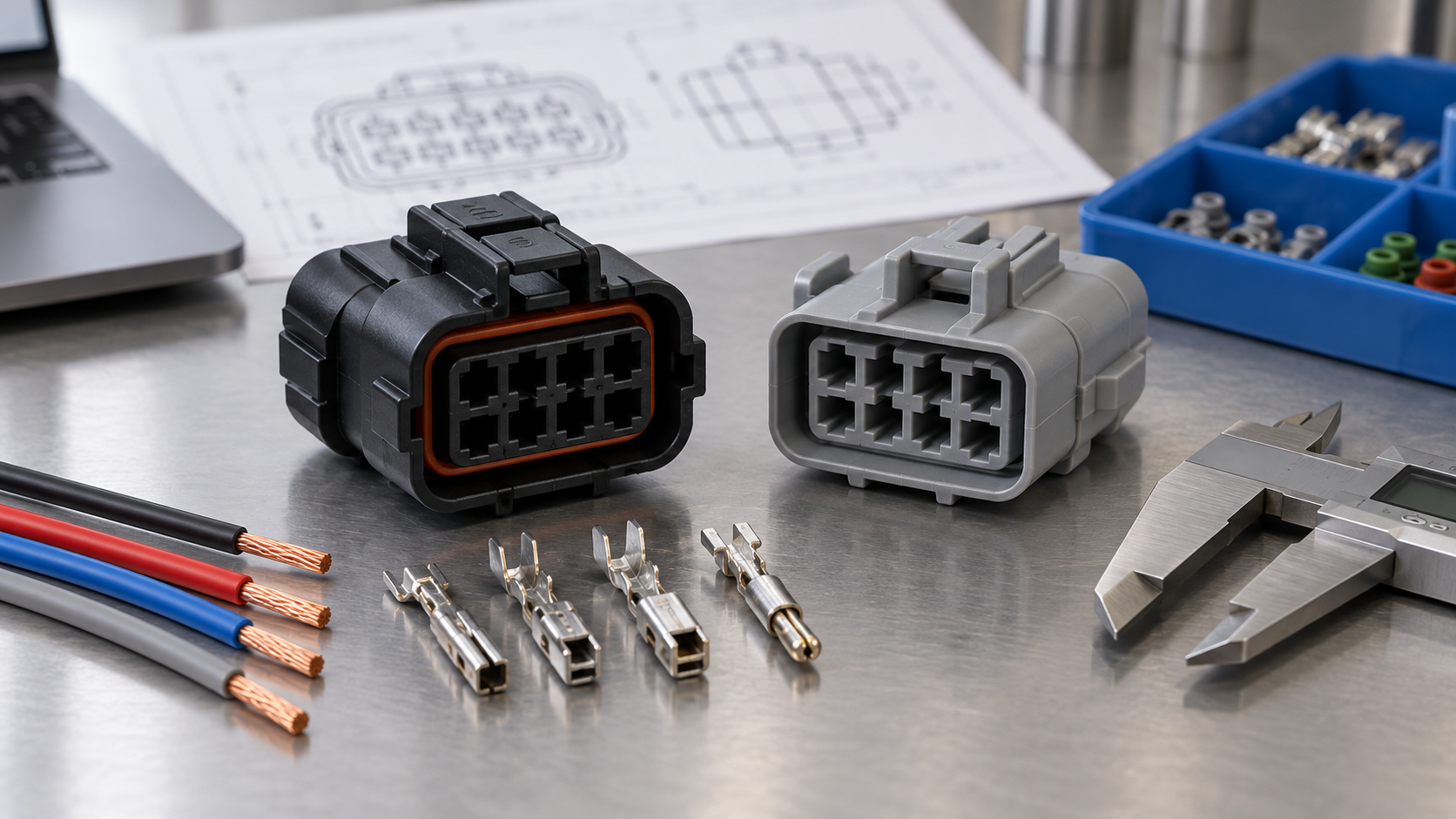
An eight-pin label tells you how many contact positions the housing is designed to accept. It does not tell you whether all positions are populated, whether every cavity uses the same terminal, or how the circuits are numbered. A compact lamp or body-control harness may combine a feed, return, control lines, and low-current signals in one housing; each circuit still needs its own wire, terminal, and validation decision.
How should you map the cavities before selecting a housing?
Start with an approved vehicle drawing, service document, or existing harness sample. Record the connector-side view used for pin numbering, populated and spare cavities, key code, latch direction, and the mating part number. Keep the vehicle-side and harness-side views separate in the drawing because mirroring a cavity map is a common source of reversed feeds and failed continuity checks.
Then build a circuit matrix for positions 1 through 8. Include nominal voltage, continuous and inrush current where relevant, signal type, duty cycle, wire cross-section, insulation diameter, temperature, and whether the circuit is safety-critical. This matrix lets a supplier confirm whether a housing supports one terminal family or a defined mixed-terminal arrangement. It also gives purchasing a controlled basis for comparing a catalogue part with an engineered variant.
| Fitment checkpoint | Evidence to request | Production risk if skipped |
|---|---|---|
| Cavity numbering | Pinout drawing, connector-side view, populated and spare positions | Reversed circuits, wrong sensor reference, rework |
| Keying and polarization | Key code, ribs, latch geometry, CPA or TPA details | Look-alike parts mate incorrectly or fail to lock |
| Mating interface | Plug and receptacle part numbers, gender terminology, mating table | Incompatible halves, incomplete insertion, terminal damage |
| Envelope and routing | Dimensions, panel clearance, cable exit, bend radius, strain relief | Harness interference, pull-out load, assembly delays |
Which terminal and wire-gauge choices matter most?
Terminal choice is determined by the circuit and the approved connector system, not by the eight-position count. Match each circuit to the terminal maker’s wire range, current guidance, crimp dimensions, plating option, and temperature conditions. Small signal contacts can sit beside larger power contacts only when the housing, terminal locks, and tooling are explicitly designed for that combination. A contact that appears to fit a cavity can still have the wrong mating interface or an unsupported crimp barrel.
Wire gauge is one input, not a substitute for a complete electrical check. Consider conductor material, insulation outside diameter, bundling, ambient temperature, duty cycle, and voltage drop. The terminal’s current capability is application-dependent; adjacent loaded cavities and heat inside a sealed enclosure can change the result. Ask for the derating conditions and test method behind any current claim instead of copying a headline value into the harness specification.
Crimp quality also controls the practical performance of an 8 pin connector automotive assembly. Use the terminal supplier’s applicator settings and inspection criteria, including conductor-brush position, insulation support, crimp height where specified, and pull-force checks. The automotive terminal crimping guide can help technicians frame the work instruction, but the approved terminal drawing remains the controlling document. Treat the 8 pin connector automotive wording as a search label only; the drawing and terminal part number govern the build.
How do terminal finishes and retention affect service life?
Tin, nickel, and gold finishes are selected for the contact system and environment; they are not interchangeable merely because the dimensions look close. Verify the mating finish, contact normal force, corrosion exposure, and any low-level signal requirements. The housing should also specify primary terminal retention and any secondary lock, often called a TPA. After crimping, a terminal must be fully seated so the secondary lock can close without forcing it over a partially inserted contact.
A controlled first-article inspection should include terminal seating, lock engagement, continuity, and a measured pull check where the application requires it. For repair programs, confirm that replacement terminals, seals, extraction tools, and inspection criteria will remain available over the expected service period.
When does a sealed 8-pin automotive connector make sense?
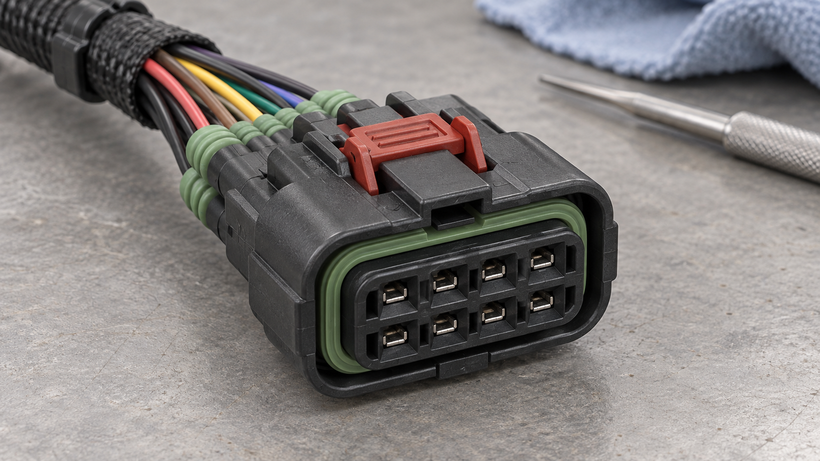
Choose a sealed design when the mated interface is exposed to splash, dust, condensation, road salt, engine-bay fluids, or repeated wash-down. Sealing is a system property: the housing, wire seal, cavity plug, back seal, cable exit, and mating latch must work together. A rubber insert alone does not establish an ingress rating. Define the exposure and the required test condition before selecting the seal architecture.
For a protected cabin or enclosed module, an unsealed design may simplify assembly and service if the vehicle specification allows it. For an exterior harness, verify the seal’s wire-diameter range, unused-cavity plugs, strain relief, and compatibility with the terminal family. Test the assembled and mated connector in its installed orientation; an unsupported harness can load a seal or latch even when a bench sample looks acceptable.
SAE USCAR-2 and the vehicle maker’s validation plan can guide mechanical, electrical, thermal, vibration, and environmental checks. IEC 61984 provides general connector safety requirements and tests, but the applicable evidence still depends on the connector type, system voltage, destination market, and customer requirements. Describe a claim such as “sealed” with its condition and method so that purchasing, quality, and service teams interpret it consistently.
How should buyers compare connector options and total cost?
Unit price is only one part of the decision. A lower-priced housing can become expensive when it requires a new applicator, extra cavity plugs, special inspection, slower assembly, or a different service kit. Compare options against the same circuit matrix and validation plan, then record assumptions so a later engineering change does not quietly invalidate the quote. This is the practical distinction between a catalogue 8 pin automotive connector and a released connector system.
| Selection dimension | Option A: protected, low-service harness | Option B: exposed or serviceable harness | Was es zu bestätigen gilt |
|---|---|---|---|
| Environment | Cabin or enclosed module | Engine bay, exterior, splash or salt | Seal architecture, cavity plugs, chemical and temperature limits |
| Circuit mix | Mostly signals with a defined feed | Mixed signal, actuator, or lighting loads | Terminal sizes, adjacent-cavity derating, fuse and wire strategy |
| Locking | Primary latch with guided keying | Latch plus CPA/TPA and stronger strain relief | Lock position, insertion force, retention and harness support |
| Service | Factory-only replacement | Field repair or repinning expected | Replacement contacts, seals, tools, instructions, and traceability |
| Cost of ownership | Standard tooling and documented assembly | Added sealing, inspection, or repair inventory | Tooling, training, validation, change control, returns and downtime |
Which application dimension should guide the shortlist?
| Application | Typical circuit question | Connector emphasis | Approval evidence |
|---|---|---|---|
| Lighting harness | Which positions carry feed, return, control, or feedback? | Terminal mix, heat, keying, vibration and service access | Circuit matrix, mating sample, thermal and retention checks |
| Sensor or actuator module | Are signals low-level, shielded, or exposed to fluid and vibration? | Contact stability, routing, seal and strain relief | Signal continuity, environmental plan and terminal specification |
| Accessory harness | Will an installer mate it repeatedly or route it through a tight space? | Polarization, latch feedback, envelope and repairability | Installation sample, mating-cycle target and service instructions |
| Body-control or cabin module | Does the housing need compact packaging with mixed loads? | Cavity map, terminal family, PCB or wire interface, documentation | Controlled drawing, crimp validation and change-notification terms |
For a broader view of connector families and contact choices, see the complete automotive electrical connector guide. Buyers evaluating rectangular housings can also review ZUCH rectangular connector options as a starting category, then confirm the exact mating and terminal specification with engineering.
What standards and compliance evidence should be in the file?
ISO 8092 is a road-vehicle wiring-harness connector standard series that addresses dimensions, performance, and related requirements for on-board electrical connections. SAE USCAR-2 is an automotive connector-system performance specification and test reference. IEC 61984 covers connector safety requirements and tests. These documents define scopes and methods; they do not automatically certify every eight-position assembly or prove that a part is suitable for a particular vehicle.
Request the revision and applicable parts of each standard cited in a quotation. Match the test plan to the destination market, vehicle maker’s quality requirements, system voltage, and installation environment. Keep material declarations, terminal and housing drawings, crimp instructions, validation reports, and change-notification terms with the approved part record. Unsupported statements about current, waterproofing, temperature, or certification can create warranty and sourcing exposure even when the connector mates on a bench. The release record for an 8 pin automotive electrical connector should identify the exact tested configuration.
ZUCH’s supplied capabilities include rectangular, RAST, FASTON, terminal, motor, and compressor connector lines. Where applicable, its documentation can be evaluated against IATF 16949:2016 quality-system requirements, CNAS laboratory accreditation, UL witness-lab arrangements, UL/CUL coverage, and PA66 or PA66 GWT material details. The buyer should still request the product-specific file and verify that the evidence applies to the exact housing, terminal, material, and market being purchased.
What should you send a connector supplier before approving samples?
- Freeze the interface: send the vehicle-side part number, mating half, key code, cavity view, envelope, and cable-exit direction.
- Attach the circuit matrix: list voltage, current, wire gauge, insulation diameter, signal type, temperature, and duty cycle for all eight positions.
- Define the environment: state cabin, engine-bay, exterior, fluid, vibration, wash-down, salt, and condensation exposure, plus the required sealing condition.
- Set the service boundary: identify whether terminals must be replaceable and which tools, seals, and repair instructions the program needs.
- Approve evidence: review drawings, material and test data, crimp settings, samples, traceability, and engineering-change controls before volume release.
Use the same checklist for every supplier. It makes an 8 pin automotive electrical connector comparison auditable and helps a distributor or harness plant identify missing data before tooling is committed. When an automotive 8 pin connector is proposed as a replacement, require the same evidence rather than accepting a pin-count match. The automotive connectors and terminals reference provides additional terminology for RFQs and service documentation.
Frequently asked questions
What is a 8-pin automotive connector typically used for in lighting, sensors and accessory harnesses?
An eight-position connector can join a lighting assembly, sensor or actuator module, body-control interface, or accessory harness to the vehicle wiring. The eight cavities may carry a mix of power, ground, control, feedback, and signal circuits. Confirm the actual pinout and current at each cavity because the pin count does not prescribe a standard circuit assignment.
How do I confirm that a 8-pin automotive connector matches my vehicle wiring?
Match the vehicle-side part number, housing family, keying, cavity numbering view, terminal type, wire range, and mating half against an approved drawing or OEM service document. Then test a sample for latch engagement, terminal seating, continuity, and the environmental requirements of its installed location. A similar outline or shared pin count is not enough evidence of compatibility.
Do 8-pin automotive connectors need a matching male and female housing?
A mated wire-to-wire system needs the specified plug and receptacle, with compatible terminals, locks, and keying. Some families use plug-and-header terminology rather than male and female, so part numbers and mating tables are more reliable than gender labels. Do not assume that two eight-position housings from different families will mate safely. The same rule applies when a proposed 8 pin connector automotive assembly is offered as a substitute.
What terminal and wire-gauge options are common for a 8-pin automotive connector?
Common systems combine small signal contacts with larger power contacts, but the allowed wire range and current guidance come from the terminal family. Tin-plated copper-alloy contacts are widely used; other finishes may be specified for the mating system or signal environment. Select each position using approved crimp, temperature, sealing, and retention data, then validate the completed harness. The exact 8 pin automotive connector specification should identify those choices cavity by cavity. That same record should state the approved 8 pin automotive electrical connector terminal and seal references.
When should I choose a sealed 8-pin automotive connector?
Choose a sealed version when the mated interface faces splash, dust, salt, condensation, fluids, or an engine-bay or exterior location. Confirm the wire-seal diameter range, cavity plugs, backshell or strain relief, and the test condition for the complete assembly. In a protected cabin, an unsealed design may be suitable when the vehicle specification permits it and service access is more important.
Can I replace one terminal in a 8-pin connector without replacing the full housing?
Often, but only when the housing is serviceable and the replacement terminal, seal, and extraction tool are approved for that family. Inspect the cavity, locking lance, secondary lock, crimp, and seal after removal; a cracked housing or damaged retention feature requires replacement of the affected part. Follow the connector maker’s service procedure instead of forcing a generic contact into the cavity.
References
- SAE USCAR-2, Performance Specification for Automotive Electrical Connector Systems.
- ISO 8092 series, Road vehicles — Connections for on-board electrical wiring harnesses.
- IEC 61984, Connectors — Safety requirements and tests.
Choosing an eight-position connector is a sequence of checks, not a pin-count shortcut. First freeze the mating interface and cavity map; then size every terminal and wire for its real circuit, select sealing and retention for the installed environment, and approve the evidence required by the destination market and vehicle program. A sample that mates is only the beginning: the file should also show crimp quality, lock engagement, continuity, retention, and the relevant environmental tests. Do not skip a drawing review or substitute a generic contact when a service repair is needed. ZUCH can help buyers compare configurable automotive 8 pin connector and terminal options against that evidence-led process; review the ZUCH product directory and contact the team with the pinout, mating part, environment, and validation requirements.