Zhejiang ZUCH Technology Co., Ltd.
A harness engineer can lose hours chasing an intermittent accessory fault after a seven-cavity connector is selected by pin count alone. The housing may mate, yet the terminal family, wire range, keying, cavity numbering, or environmental protection can still be wrong. ISO 8092 covers connection systems used in road-vehicle wiring, but it does not give every vehicle a universal seven-pin pinout. That distinction matters: a connector that looks right can still create miswires, rework, water ingress, or a costly return. This guide explains how to compare a 7 pin automotive connector, confirm its wiring, choose terminals and seals, and decide whether a repair can be limited to one contact.
Zusammenfassung: Treat “seven pin” as a cavity count, not a compatibility claim. Start with the vehicle or harness drawing, then verify keying, mating half, terminal system, wire range, current and voltage requirements, retention, and the exposure zone. ISO 8092 and OEM or USCAR requirements can define test and interface expectations, while the actual pin assignment remains application-specific. For procurement, request the housing and terminal part numbers together, a pinout or cavity map, material and flammability information where relevant, and evidence of validation. A sealed design is justified by water, splash, mud, or spray exposure; it is not automatically better in a dry cabin harness.
What does “seven pin” actually tell you?
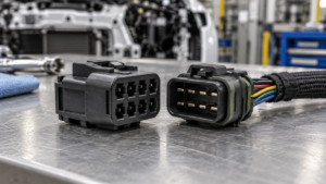
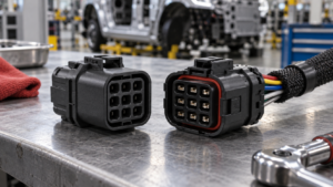
It tells you that the connector has seven electrical positions or cavities. It does not identify the connector series, terminal size, gender, polarization, seal system, or pin numbering convention. Two seven-position housings can have different centerlines, locks, keying, contact arrangements, and allowable wire sizes. For buyers comparing a 7 pin automotive connector, that distinction prevents a cavity count from being mistaken for a part-number match. Even within one family, a populated seven-way assembly may use fewer circuits than the housing can accommodate, with blank cavities or plugs retained for a future option.
Pin count also says nothing about circuit function. A seven-way assembly might serve a body-control module, HVAC actuator, sensor group, lighting accessory, or motor sub-harness. The correct choice follows the electrical and packaging requirements of that circuit. Confirm the mating interface and cavity map from the vehicle service information, released harness drawing, or the original connector before ordering replacements.
Which specifications should buyers compare?
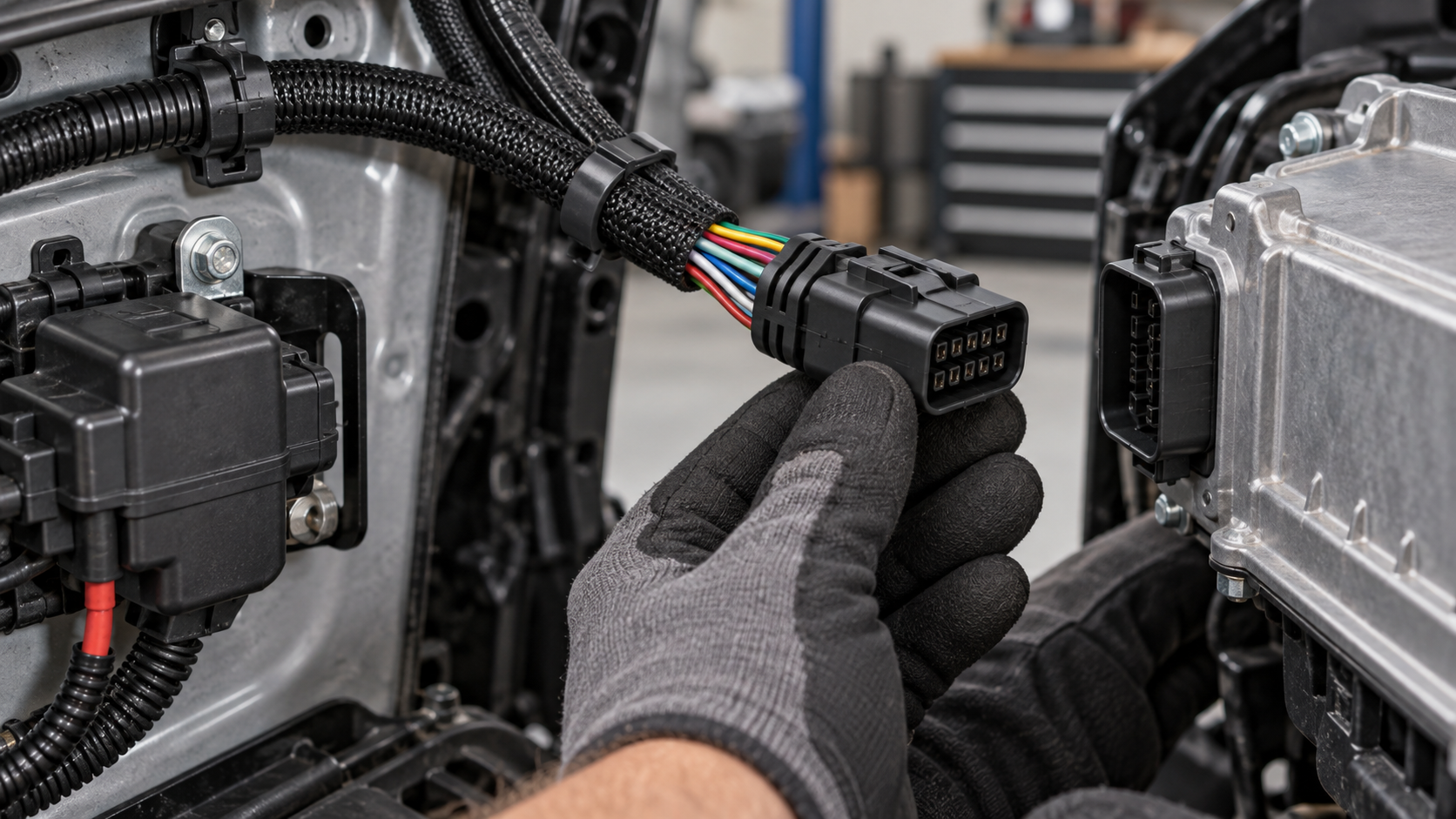
A useful comparison separates interface fit from operating conditions. The following table is a screening tool; values must come from the selected series drawing and the vehicle specification rather than from the number of pins.
| Selection dimension | What to verify | Why it changes the decision |
|---|---|---|
| Mechanical interface | Housing outline, cavity pitch, polarization, latch, CPA or secondary lock, and mating half | Prevents a visually similar housing from being forced into a harness or losing retention under vibration. |
| Electrical duty | Per-circuit voltage, current, signal type, and any inrush or motor load; compare with the terminal and wire system rating | A seven-cavity connector can carry mixed low-level signals and power only when the series permits that combination. |
| Terminal system | Male or female contact, contact size, plating, crimp envelope, and approved conductor range | The housing and terminal are a matched system; an attractive housing is unusable if the contact cannot be crimped to the harness wire. |
| Environment | Cabin, engine-bay, underbody, spray, dust, temperature cycle, chemicals, and pressure-wash exposure | Determines whether seals, cavity plugs, a positive lock, and a validated material system are needed. |
| Serviceability | Terminal release access, replacement contacts, repair-wire availability, and inspection method | Service teams can repair one circuit without replacing a complete harness when the series supports depinning and re-termination. |
| Documentation | Controlled drawing, cavity numbering, assembly instructions, crimp specification, and change history | Traceable documentation reduces line-side variation and prevents a connector revision from silently changing the pinout. |
How should the mating pair and keying be checked?
Specify the plug and receptacle as a pair, including any mounting clip, CPA, backshell, seal, or cavity plug. A “male connector” may describe the housing or the contact, and suppliers can use those terms differently. The drawing should show the view used for cavity numbering—mating face, wire side, or service view—because reversing that view is a common source of harness errors.
Check polarization and keying before samples arrive at the line. A connector that can be inserted in more than one orientation, or that mates with a neighboring family, increases the risk of an assembly escape. Where a vehicle uses multiple variants, record the key code and populated cavities in the bill of materials.
When is a sealed housing the right choice?
Sealing is an exposure decision. In an engine compartment, wheel area, exterior sensor location, or a harness routed through a splash zone, the design may need individual wire seals, interface seals, cavity plugs, and a secondary lock. The required protection level must be demonstrated for the specific assembly and test conditions; a generic “waterproof” label is not a substitute for a specification.
For a dry interior or protected electronics enclosure, an unsealed connector can reduce parts and service complexity when the application specification allows it. Adding seals can affect terminal insertion force, wire-size compatibility, tooling, and repair procedure. Ask for the series’ sealing instructions and verify that the chosen seal matches the conductor insulation diameter. A housing that accepts seven terminals but leaves unused cavities must also have the correct plugs for those positions.
Which terminal and wire-gauge details prevent rework?
Wire gauge is only one input. The approved conductor cross-section, insulation diameter, strand construction, terminal material and plating, crimp height, bellmouth, and pull-out requirement must be read together. The crimp should be made with the specified applicator or an approved equivalent, then checked using the supplier’s measurement and inspection method. The automotive terminal crimping guide is a useful process reference, but the connector family’s controlled drawing remains the governing document.
Terminal gender and housing gender should be recorded separately in the BOM. A female contact can sit in a plug housing, while a male blade can sit in a receptacle housing, depending on the series. For mixed circuits, verify whether the family allows different contact sizes or whether all seven positions share one terminal system. Do not infer an allowable wire gauge from a photograph or from another seven-pin product.
How do standards and supplier evidence support approval?
ISO 8092 provides terminology and requirements for road-vehicle electrical connection systems; it is a framework for design and testing, not a universal pinout catalogue. USCAR-2 is an automotive connector performance specification used in industry qualification work, while OEM drawings may add vibration, temperature, sealing, or retention requirements. IEC or SAE documents may apply to a particular vehicle subsystem or test method. Identify the exact edition and scope in the validation plan.
Ask the supplier to distinguish a product certification from a laboratory or management-system credential. ZUCH’s supplied company information includes IATF 16949:2016, CNAS laboratory accreditation, a UL witness laboratory, UL/CUL coverage, and PA66 or PA66 GWT materials where applicable. Those credentials support a sourcing review, but they do not make every seven-pin configuration automatically compliant. The selected part number, material, terminal, and destination-market requirements still need approval.
How do common connector choices compare?
This table compares decision patterns rather than claiming a universal winner. Use the application drawing and validation plan to confirm each row.
| Choice pattern | Compatibility and performance focus | Cost and service tendency | Typical fit |
|---|---|---|---|
| Unsealed seven-way housing | Keying, retention, terminal fit, and protected location | Fewer sealing parts; straightforward depinning when documented | Cabin or enclosed modules where the exposure specification permits |
| Sealed seven-way housing | Interface and wire seals, cavity plugs, drainage and validated environmental tests | More components and process controls; lower water-ingress risk when correctly specified | Engine-bay, exterior, splash, or contaminated locations |
| Pre-terminated repair assembly | Supplier-controlled crimp and wire length; verify pinout and insulation size | Fast field repair; may carry a higher piece cost and less length flexibility | Service replacement where the original housing remains sound |
| Loose housing and terminals | Full control of cavity population, wire routing, and terminal selection | Lower component flexibility but higher tooling and inspection responsibility | Production harnesses with approved applicators and controlled work instructions |
What should be verified during repair or incoming inspection?
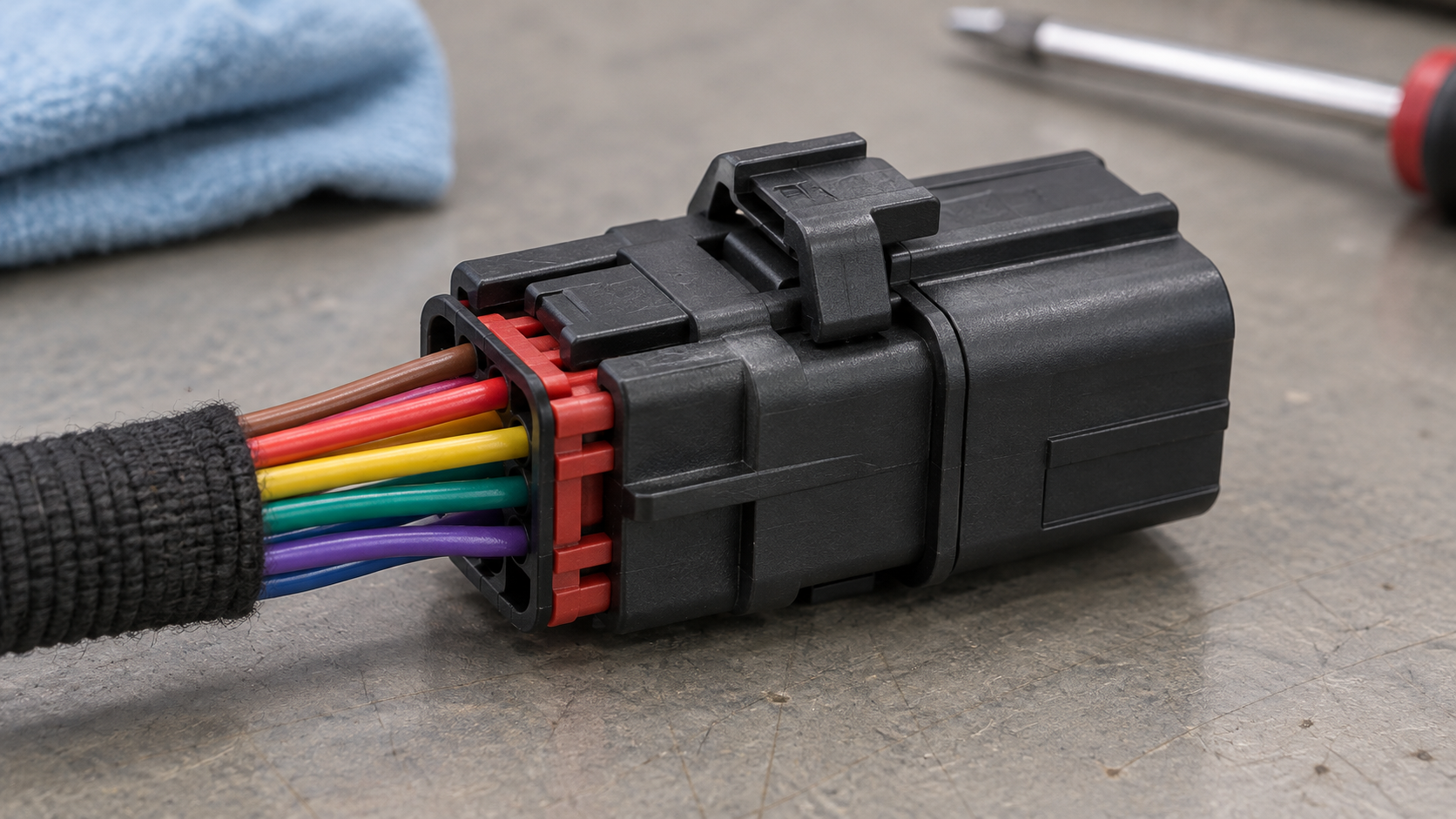
A repair decision should be based on the failed element, not on the connector’s pin count. Use the following checks before ordering a housing or cutting a harness.
| Beobachteter Zustand | Verification action | Repair boundary |
|---|---|---|
| One loose, corroded, or overheated contact | Compare cavity number, terminal part number, crimp area, and wire condition; inspect mating contact and lock | Replace the terminal or approved repair wire if the housing, lock, and mating interface pass inspection. |
| Broken latch, CPA, seal, or housing key | Check housing retention and evidence of mis-mating or water entry | Replace the housing and any single-use seals or locks; do not rely on a tie-wrap to restore primary retention. |
| Multiple heat-damaged cavities | Measure the circuit load and inspect crimp compression, terminal contact, and wire gauge | Find the overload or high-resistance cause before installing a replacement connector. |
| Unknown pinout or donor connector | Trace each conductor against the released diagram; confirm view orientation and key code | Pause the repair until identity and cavity mapping are documented. |
| Water or chemical contamination | Inspect seals, cavity plugs, backshell routing, and the surrounding harness | Replace damaged sealing parts and address the ingress path; a new dry housing alone may not solve the failure. |
What is a practical procurement checklist?
- Send the supplier the vehicle or harness drawing, mating-half reference, cavity map, key code, and populated-circuit count.
- State the wire construction, conductor range, insulation diameter, circuit duty, temperature zone, and expected environmental exposure.
- Request the controlled housing, terminal, seal, cavity-plug, and tooling part numbers as one compatible set.
- Define the acceptance plan: visual crimp criteria, retention, continuity, dimensional checks, environmental tests, and documentation.
- Approve a first article against the released drawing and record any substitution or revision before production release.
For a broader view of connector families, see ZUCH’s product directory and its rectangular connector category. ZUCH manufactures rectangular, RAST, FASTON, terminal, motor, and compressor connector lines; its quality and laboratory credentials can be reviewed alongside the exact configuration being quoted.
Frequently asked questions
What is a 7-pin automotive connector typically used for in mid-size control and accessory circuits?
It is commonly used where a harness needs seven separately retained circuits, such as a body-control sub-harness, actuator group, sensor set, or accessory module. The use case depends on the vehicle drawing and electrical load; seven pins alone do not identify the function. Confirm the circuit map and terminal rating before substitution.
How do I confirm that a 7-pin automotive connector matches my vehicle wiring?
Match the housing and key code, mating half, cavity numbering view, populated positions, terminal family, wire range, and seal system to the released harness information. Compare the original part number or a service diagram, then verify continuity before connecting power. A visual fit is only an initial check.
Do 7-pin automotive connectors need a matching male and female housing?
Yes, the two mating housings and their contacts must belong to a compatible series and keying configuration. “Male” and “female” can refer to contacts or housings, so use the supplier’s part-number terminology and mating table. Order the pair with any required CPA, backshell, seal, or mounting feature.
What terminal and wire-gauge options are common for a 7-pin automotive connector?
Options vary by series and include different contact sizes, plating choices, conductor cross-sections, and insulation diameters. The approved range is set by the terminal drawing and crimp specification, not by the seven-way format. See ZUCH’s guide to automotive connectors and terminals when building a comparison, then confirm the selected series documents.
When should I choose a sealed 7-pin automotive connector?
Choose a sealed system when the connector sits in a splash, spray, dust, mud, or outdoor exposure zone defined by the vehicle requirement. Confirm that wire seals, interface seals, cavity plugs, and the housing have been validated together. For protected cabin locations, sealing may add process and service steps without solving a real exposure problem.
Can I replace one terminal in a 7-pin connector without replacing the full housing?
Often, yes, if the housing lock, cavity, keying, and mating interface are undamaged and the terminal is available as an approved service part. Use the specified release tool, preserve cavity identity, re-crimp to the documented method, and perform continuity and retention checks. Replace the housing when heat, chemical attack, broken locks, or seal damage compromises its function.
References
- ISO, ISO 8092 Road vehicles — Connections for on-board electrical wiring harnesses, current applicable parts and edition: iso.org/standard/52245.html.
- United States Council for Automotive Research (USCAR), USCAR-2 Performance Specification for Automotive Electrical Connector Systems: uscar.org.
- SAE International, automotive electrical connection and component test standards catalogue: sae.org/standards.
- IEC 61984, Connectors — Safety requirements and tests: webstore.iec.ch/en/publication/6040.
Conclusion
A seven-cavity housing is only the starting point for selecting a 7 pin automotive connector. The reliable decision sequence is to identify the mating interface and cavity map, confirm terminal and wire compatibility, match sealing to the actual exposure zone, and then validate retention, continuity, crimp quality, and the applicable vehicle requirements. Do not skip the drawing view or assume that ISO 8092 or a supplier credential supplies a universal pinout; those shortcuts create avoidable assembly and service risk. ZUCH can support this review with rectangular, RAST, FASTON, and terminal connector lines, plus IATF 16949:2016, CNAS laboratory accreditation, UL witness-laboratory capability, and applicable UL/CUL and PA66/PA66 GWT documentation. Buyers can start with the ZUCH product directory and contact the technical team with the released harness data for a configuration check.