Zhejiang ZUCH Technology Co., Ltd.
Consider this repair scenario: when a technician in Nagoya orders a replacement plug for a Mitsubishi lighting circuit using only a photograph, the housing arrives but its keying prevents full engagement. The original connector may indeed be damaged, yet the immediate purchasing mistake is an incomplete part identification. A vehicle badge and a similar outline cannot establish the mating interface, contact system or circuit assignment.
Zusammenfassung: Identify Mitsubishi automotive electrical connectors through three separate records: vehicle application, connector hardware and wiring diagram. Match the housing, terminals and seals before choosing a repair pigtail. IEC 60512-1 describes a framework for connector tests; it does not supply a universal Mitsubishi pinout. The vehicle manufacturer’s service procedure determines the permitted repair and checks.
This guide concerns ordinary low-voltage harness identification. Traction-battery, airbag and other restricted circuits require their own service procedures and qualified personnel. Mitsubishi’s service-information portal is an appropriate starting point for the vehicles and markets it covers; a regional portal should not be assumed to cover every imported model.
Which records identify the correct Mitsubishi connector?
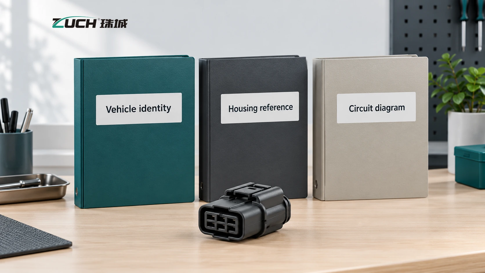
Begin with the vehicle identification number or applicable chassis reference, build date, engine or powertrain, sales market and exact component location. Then record the housing markings, cavity arrangement, latch position and visible polarization features. A number molded into plastic may identify a mold or material rather than an orderable service part, so confirm what the reference actually represents.
The third record is the circuit diagram and connector-view reference. A component supplier number can identify a sensor while the harness-side plug has a different service reference. Keep those two numbers in separate fields. The Mitsubishi service-information portal provides a route to manufacturer information; this article does not reproduce a model-specific wiring diagram or assert that a particular replacement is approved.
Photograph the undisturbed installation, housing markings, mating side and wire-entry side when safely accessible. Include a scale beside the part for identification, without inserting an unsuitable measuring tool into the contacts. The photographs support a drawing comparison; they do not replace it. Ask the supplier to identify the proposed housing and its specified mating component in writing.
How should the connector view be matched to the wiring diagram?
Check whether the drawing is viewed from the mating face or wire side before recording cavity positions. The two views reverse the apparent layout. A photograph can also become misleading when an image editor or messaging application mirrors it. Preserve the original image orientation and use the drawing’s latch or locating feature as a reference.
A cavity number describes a physical position; it does not independently define voltage, polarity or function. Two similar housings can carry different circuits. Use the vehicle-specific circuit reference and the component designation together. The distinction is explained further in the guide to automotive connector pinouts.
Do not establish an unknown circuit by applying power to candidate terminals. Follow the manufacturer’s isolation, probing and diagnostic instructions, including restrictions on disconnecting modules or testing sensitive circuits. The UK Health and Safety Executive also stresses the importance of manufacturer-specific information when working around electric and hybrid systems; switching a vehicle off does not prove that stored energy is absent.
When should a housing repair become a pigtail repair?
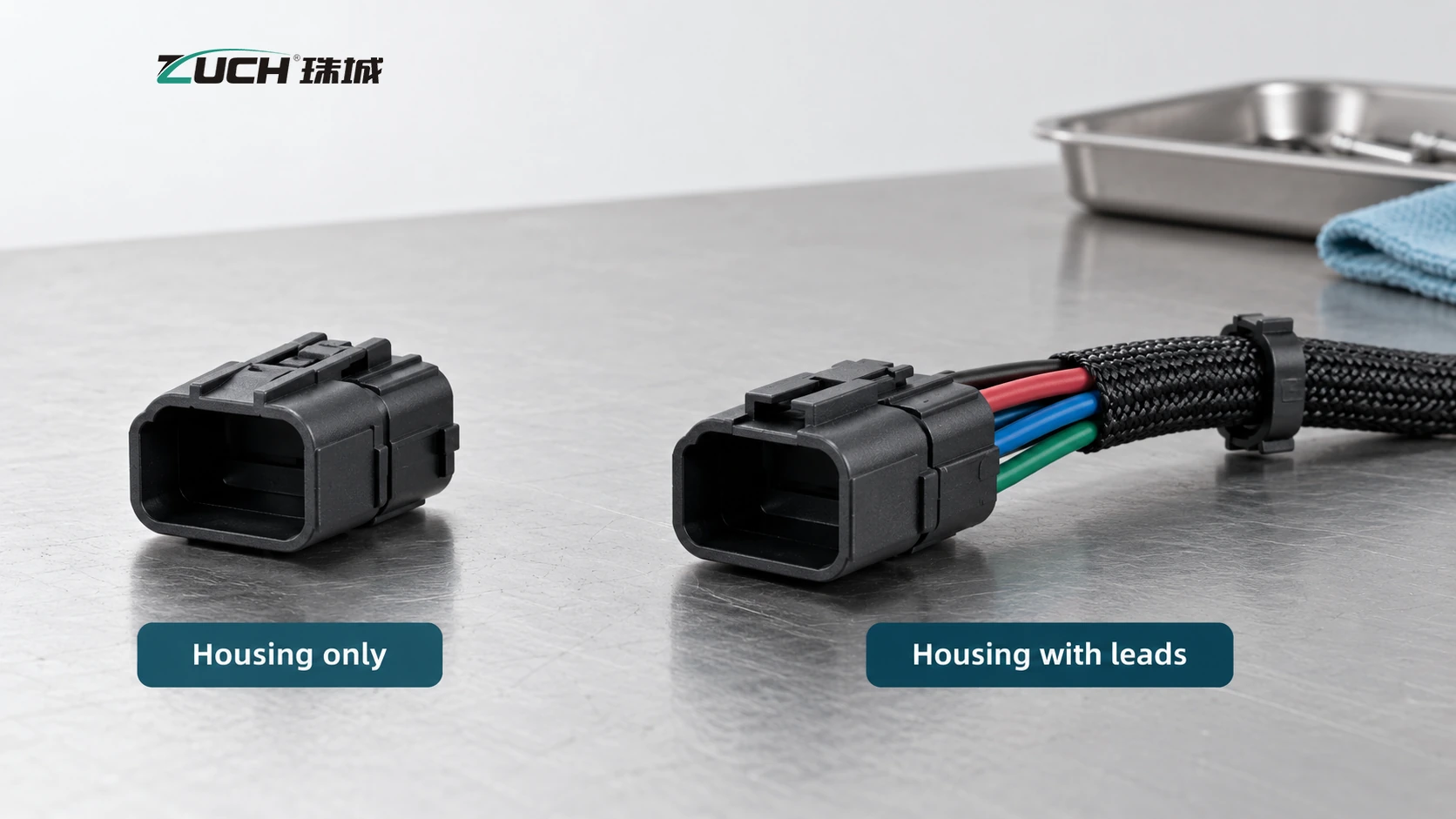
The repair scope depends on the damaged components. A broken latch with serviceable contacts and intact wire may permit housing replacement when the manufacturer allows it. Corroded contacts, heat damage, weakened retention or deteriorated adjacent wire can require a wider repair. Inspect the mating half as well: replacing one side leaves the cause unresolved if the other side remains damaged.
| Repair option | When it may be appropriate | What must be verified |
|---|---|---|
| Housing replacement | Damage is confined to the shell and the approved procedure permits transfer | Exact housing revision, terminal condition, retention and cavity map |
| Individual terminal replacement | A serviceable housing can accept the specified replacement contact | Terminal part number, conductor range, plating, seal and tool |
| Repair pigtail | The connector and adjacent lead section need replacement | Lead specification, circuit mapping and approved joining method |
| Harness replacement | Damage extends beyond the permitted local repair | Manufacturer criteria, affected branches and root cause |
For Mitsubishi automotive electrical connectors, a pigtail advertised for a model name is only a candidate. Match the engine, build range and device reference. Lead colours on a replacement pigtail may differ from the original loom, so they cannot substitute for a verified cavity-to-circuit record.
Which terminal and seal details belong on the order?
Specify the complete connection rather than the shell alone. Aptiv’s connection-systems portfolio, for example, distinguishes connectors, terminals, seals and headers. That product structure demonstrates why these items need separate identification; it does not establish that an Aptiv part is fitted to, or interchangeable with, a particular Mitsubishi application.
| Order field | Evidence to request | Problem prevented |
|---|---|---|
| Housing and mating reference | Drawing, keying and revision | A shell that looks correct but will not engage |
| Terminal and wire | Specified contact, conductor range and insulation range | A mechanically unsuitable termination |
| Sealing components | Wire seal, interface seal and unused-cavity requirements | An incomplete sealing arrangement |
| Tooling and repair method | Application specification and service procedure | Damage from an inappropriate extraction or crimp tool |
| Supply traceability | Manufacturer reference, batch and source | An unidentifiable substitution on the next order |
Wire size alone is insufficient for seal selection because wires with the same conductor area can have different insulation diameters. The wire-seal and cavity-plug guide explains those separate checks. Do not assume that a seal can be reused after terminal removal; use the specified inspection and replacement criteria.
What evidence is needed before accepting the repair?
IEC 60512-1:2018 provides a general basis for connector tests and measurements, with the detailed product specification defining applicable tests, severity and permissible limits. A reference to the standard is therefore not a repair approval. Similarly, an ingress-protection claim must identify the tested assembly and condition; the word “waterproof” in a listing cannot establish performance after wires or seals have been changed.
Record the parts installed, cavity mapping, terminal seating, secondary-lock engagement, sealing arrangement and harness routing. Complete the vehicle-prescribed electrical and functional checks. A continuity result alone cannot establish that a loaded contact will remain satisfactory or that the assembly will exclude moisture. Avoid imposing an invented universal resistance limit on every circuit.
For a repeat supply enquiry, submit these records with the required quantity and documentation. ZUCH’s rectangular connectors can be reviewed against an engineering specification, but catalog presence does not prove Mitsubishi fitment or vehicle-manufacturer approval.
Frequently asked questions
How do I identify a Mitsubishi automotive electrical connector?
Start with the VIN or applicable chassis reference, build date, powertrain and component location. Compare the housing markings, keying, cavity arrangement and mating reference with the correct service information. A photograph or molded number helps identification but may not be sufficient to establish an orderable service part.
Can I use a repair pigtail for a Mitsubishi connector?
A repair pigtail may be suitable when the vehicle manufacturer permits that repair and the supplied housing, terminals, wire and seals meet the application requirements. Confirm the affected circuit and approved joining method. Do not assume replacement wire colours match the original circuit assignments.
How do I find the pinout for a Mitsubishi connector?
Use the wiring diagram and connector-view reference for the exact vehicle, market and build. Check whether the view is from the mating face or wire side, then map cavity numbers to the named circuits. Do not infer polarity from connector shape or test an unidentified circuit by applying power.
Are Mitsubishi connector housings model-specific?
Some connector families may be used across several applications, while keying, contacts or service references differ by model, build or device. A shared outline does not establish compatibility. Confirm the specific mating interface and application rather than treating every Mitsubishi housing as either universal or unique to one model.
What causes a Mitsubishi connector terminal to corrode?
Moisture, damaged or incorrect sealing parts, contamination and deterioration of protective surfaces can contribute to corrosion. Inspect the mating half, wire-entry area and adjacent conductor to determine the repair scope. Replacing the visible terminal without correcting the ingress path or damaged wire can leave the underlying problem unresolved.
How do I test a Mitsubishi connector after repair?
Follow the vehicle-specific repair and diagnostic procedure. Verify cavity mapping, terminal retention, locks, seals and routing, then perform the prescribed electrical and functional checks. Continuity alone does not prove satisfactory performance under load or confirm that the repaired assembly retains its intended sealing.
References
- Mitsubishi Motors North America: service-information portal and regional coverage
- IEC 60512-1:2018: connector tests and measurements, general specification
- Aptiv: connection systems and distinct low-voltage, high-voltage and data product groups
- UK Health and Safety Executive: electric and hybrid vehicle repair guidance
Sources checked on 26 October 2026. Illustrations show generic examples and do not establish product fitment or approval.
What to take away
Correctly identifying Mitsubishi automotive electrical connectors requires agreement between the vehicle record, connector hardware and circuit diagram. Choose the repair scope only after inspecting the contacts, wires, seals and mating half; a new shell cannot resolve damage that remains elsewhere in the connection.
For a specification-based ZUCH enquiry, send the housing reference, mating details and required quantity. Any proposed item must be assessed against the application; no Mitsubishi approval or interchangeability is implied.