Zhejiang ZUCH Technology Co., Ltd.
Illustrative scenario: When an appliance engineer in Stuttgart fitted a new harness to a control-board prototype, the plug appeared to align and the first powered unit ran. Minutes later, an intermittent circuit stopped the test. The connector was not simply “bad”: the purchasing description had named a RAST family but had not fixed the mating drawing, coding, terminal, wire, or assembly process.
Zusammenfassung: RAST 2.5 and RAST 5 refer to nominal 2.5 mm and 5.0 mm interface grids, but that distinction alone does not establish current capacity or cross-brand compatibility. Treat RAST as an appliance-connector ecosystem, not one universal plug. Freeze the complete mating pair, coding, termination and test plan before approval; use the applicable ZVEI RAST interface specification, supplier drawings and configuration-matched evidence as the controlling documents.
RAST Names Describe an Interface Family, Not a Universal Cross-Mating Guarantee
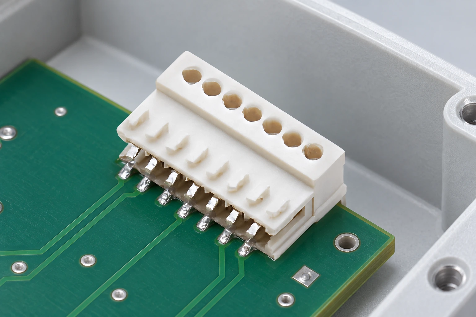
RAST connectors are widely used to organize wire-to-board connections in appliances and related equipment. Public product portfolios show receptacles, PCB headers and board-edge arrangements sold under the RAST name by more than one manufacturer. That common vocabulary helps engineers define architecture, but it does not turn every product carrying the family label into an interchangeable part. A bridge combination connector is another interface that needs identification by its drawing rather than by its family label.
A valid equivalence decision has several layers: contact pitch and geometry; housing datum and envelope; polarization; coding ribs, slots or keys; latch position; PCB thickness or header dimensions; terminal geometry; wire range; and process requirements. The approved drawing and its revision therefore outrank a family-name match, a photograph or a distributor filter.
Direct and indirect mating change what must be controlled
In direct mating, the harness-side connector engages a compatible PCB contact pattern or board edge. The PCB becomes part of the connector interface, so board thickness, copper/contact geometry, edge treatment, tolerances, insertion direction and retention features must all be specified. In indirect mating, the harness-side connector mates to a separate PCB header; the header part number, orientation, solder-tail pattern and retention become additional controlled items.

Direct mating may reduce component count, while a header may provide a replaceable interface and more routing choices. The decision should follow the board, service and assembly constraints.
Coding and polarization are system requirements
Polarization is intended to prevent reversed orientation; coding is intended to prevent a connector from reaching the wrong mating location among similar interfaces. A color stripe can help an operator, but visual identification is not a substitute for mechanical keying where a misconnection can create a hazardous or costly failure. The coding plan should be checked across the entire appliance, including service replacements and supplier alternatives.
The same rule applies to IDC and crimp. Some RAST product lines use insulation displacement connections, and others use crimp contacts. “RAST” does not prove either termination. Confirm the exact terminal, conductor construction, insulation range, wire preparation, approved tool and inspection limits for the selected part number.
RAST 2.5 Versus RAST 5 Is a First Filter, Not a Complete Selection
The numeric family distinction is useful: industry product documentation presents RAST 2.5 on a nominal 2.5 mm pitch and RAST 5 on a nominal 5.0 mm pitch. Catalogs commonly position the smaller family toward compact signal or lower-power connections and the larger family toward larger conductors or higher-power circuits. That is a portfolio tendency—not permission to assign a current, voltage, temperature or wire rating without the exact product specification. Likewise, a dimensional label such as 187 all-in-one connector is a starting point for identification, not proof of a compatible mate.
| Decision dimension | RAST 2.5 starting point | RAST 5 starting point | What still controls approval |
|---|---|---|---|
| Nominal grid | 2.5 mm family | 5.0 mm family | Dimensioned interface drawing and tolerances |
| Typical portfolio role | Compact signal or lower-power connections | Power-oriented or larger-conductor connections | Per-circuit current, temperature-rise data and derating |
| Mating arrangement | Direct or indirect variants exist in industry portfolios | Indirect variants are common; other arrangements are product-specific | Exact receptacle, PCB edge or header combination |
| Termination | IDC is available in some lines | IDC and crimp products exist across supplier portfolios | Terminal-to-wire and tooling documentation for the ordered part |
| Coding and locking | Configuration-specific | Configuration-specific | Coding matrix, latch design and whole-appliance error-proofing review |
| Compatibility conclusion | No conclusion from family name alone | Matched drawings, samples and configuration-matched validation | |
Catalog terms such as “Power,” “R5,” “D,” or supplier-specific series names may identify subfamilies, but they are not universal compatibility classes. Treat each as supplier-defined until drawings demonstrate otherwise.
A Five-Step Buyer Workflow Turns a Family Name Into a Controlled Interface
- Freeze the circuit and risk case. Record load type, continuous and transient current, duty cycle, ambient and internal temperature, pollution or condensation, vibration, mating cycles, accessible-live-part concerns and foreseeable misconnection. Do not begin with a catalog current number.
- Define the complete interface. Identify the receptacle, terminal, header or PCB edge, orientation, latch, key code, contact position map and PCB constraints on one controlled interface document.
- Define the wire and termination process. State conductor material and construction, cross-section, insulation diameter and material, strip length for crimp where required, or IDC insertion setup. Lock the approved applicator and wear-part schedule.
- Request traceable evidence. Ask for drawings, specifications, derating or temperature-rise conditions, material declarations and relevant test reports tied to the exact part numbers and configuration. A family brochure cannot validate an ordered combination.
- Validate production-representative assemblies. Test parts made with production wire, tooling, PCB finish and process settings. Record lot identity and acceptance limits so a later change can be evaluated against the same baseline.
The hidden cost is rarely the connector unit price alone. A wrong key can stop final assembly; an uncontrolled termination can create intermittent resistance; an unsupported substitution can force harness and PCB rework. For an illustrative comparison, a small piece-price saving becomes negative if even one batch requires sorting, retesting and line interruption. Total-cost review should therefore include tooling, change control, inspection, scrap, service access and second-source validation.
| Unverified item | Possible failure mode | Evidence to request | Configuration-level check |
|---|---|---|---|
| Pitch, tabs, datum and envelope | No mate, shallow engagement or contact damage | Both mating drawings and PCB specification | Dimensional review plus sample mating |
| Polarization, code and latch | Mis-mating, reverse insertion or incomplete lock | Coding matrix and latch dimensions | Error-proofing trial across all nearby connectors |
| Terminal, wire and tooling | High resistance, conductor damage or pull-out | Application specification and tool setup limits | Crimp or IDC section review, pull test and electrical test |
| Current, ambient and grouping | Excess temperature rise or insulation ageing | Rating conditions and derating data | Temperature-rise test in the appliance arrangement |
| Board retention and routing | Pad, solder-joint or contact stress | Insertion/withdrawal and retention requirements | Mating-force, mechanical-operation and vibration plan |
| Safety or material claim | Unsupported compliance file or market delay | Report or certificate with issuer, part number, revision and scope | Appliance-level safety review for destination market |
Standards Define Test Scope; They Do Not Certify an Unverified Assembly
ZVEI RAST specifications: use the applicable RAST interface document and revision to define the relevant family geometry, coding and mating rules. Because access and revisions can vary, procurement should require the supplier to identify the exact specification and drawing revision used. A statement such as “RAST compatible” without this traceability is incomplete.
IEC 60335-1: the 2020 edition, with later amendment activity, sets general safety requirements for household and similar electrical appliances. It is an appliance standard, not a blanket connector approval. Connector temperature, insulation, resistance to heat/fire and accessibility are evaluated in the end-product context with the applicable appliance part-2 standard and market requirements.
IEC 60512: this series supplies connector test and measurement methods. IEC 60512-1 explains that a detail product specification must select the tests, severities and performance limits. Useful categories can include contact resistance, mechanical operation, insertion/withdrawal forces, vibration and climatic exposure, but merely naming the series does not define an acceptance plan. For resistance-focused context, see this explanation of how contact resistance affects connector performance.
IEC 60352: IEC 60352-2:2024 addresses solderless crimped connections, while IEC 60352-4:2020 addresses non-accessible insulation-displacement connections. Their published scopes include test methods and practical guidance; they do not mean every RAST connector accepts every conductor inside the standards’ broad ranges. The component application specification and validated production process remain decisive.
For supplier qualification, begin with ZUCH’s broader connector portfolio and appliance connection context, then narrow the request to an exact interface. ZUCH should be evaluated in the same evidence-led way as any supplier: matched drawings, part-number-specific data and samples first. No certification or interchangeability is implied by the RAST name.
Frequently Asked Questions About RAST Series Connectors
Are all RAST connectors interchangeable?
No. A shared RAST designation may indicate a related interface concept or grid, but compatibility also depends on geometry, keying, polarization, latch, terminal, board or header and tolerances. Approve interchangeability only after a drawing-level comparison and tests on the intended combination.
What is the practical difference between RAST 2.5 and RAST 5?
The numbers identify nominal 2.5 mm and 5.0 mm pitch families. RAST 2.5 is commonly used where compact signal or lower-power connections are needed, while RAST 5 portfolios commonly address larger conductors or power circuits. Exact electrical and environmental ratings remain part-number-specific.
What is direct mating in a RAST connector system?
Direct mating means the harness connector engages a compatible PCB contact pattern or board edge without a separate header. The PCB thickness, finish, geometry and tolerances then become controlled connector-interface characteristics. Confirm that the exact connector series supports the intended direct interface.
Should an appliance harness use IDC or crimp termination?
Choose according to the validated connector series, wire set, volume, tooling and quality controls. IDC can consolidate wire insertion in suitable high-volume processes; crimp supports discrete terminated contacts but requires controlled strip, crimp and insertion operations. IEC 60352 methods can support process qualification, but the supplier’s application specification defines the permitted combination.
What documents should a buyer request before ordering RAST connectors?
Request mating-component drawings, coding and polarization details, terminal and wire ranges, approved tooling instructions, ratings with test conditions, relevant reports tied to exact part numbers, and change-control terms. If a second source is required, add a documented equivalence review and configuration-level validation rather than relying on a cross-reference alone.
Authoritative References
- ZVEI, The World of Connectors—Technologies and Trends, industry context and connector terminology.
- Molex, RAST-Verbinder, public industry portfolio illustrating family names, pitches, mating and termination variants.
- IEC, IEC 60335-1:2020, household and similar electrical appliance safety—general requirements.
- IEC, IEC 60512-1:2018, connector tests and measurements—generic specification.
- IEC, IEC 60352-2:2024 for crimped connections and IEC 60352-4:2020 for non-accessible insulation-displacement connections.
The durable sourcing principle is simple: the family name starts the conversation; the controlled drawing and matched test evidence finish it.
Review the available RAST connectors, then contact ZUCH with the mating drawing, circuit map, wire specification, coding requirement and validation target for a configuration-focused discussion.