Wafer Connectors: A Practical Guide to Board-to-Wire Applications
A board-to-wire connector can match the measured pitch and circuit count yet still be wrong for the harness. The missing information may be the mating housing, contact geometry, terminal retention feature or wire insulation diameter. A pitch-only purchase request leaves those decisions to assumptions, which can lead to layout rework, assembly rejection or a connection that passes continuity but moves under cable load. The practical question is therefore not simply which wafer fits the board, but which documented board-header, housing, terminal and wire combination can be assembled, serviced and validated together. This guide explains how to specify that combination before requesting samples or approving production.
The short answer is that a wafer connector links a board header to a crimped-wire housing, so the interface is only as good as all three elements together. Define board side, wire side and locking as one system. Pitch is a spacing dimension, not evidence of interchangeability. Request the complete mating-pair documentation, approved terminal-to-wire and tooling combinations, and an application-specific test plan. IEC 60512-1:2018 distinguishes test methods from the detailed product specification that selects severity and permissible limits. This approach suits internal board-to-wire connections; sealing, external exposure or safety-related use requires additional evidence for the actual configuration.
Inhalt
What is a wafer connector, and what must mate with it?
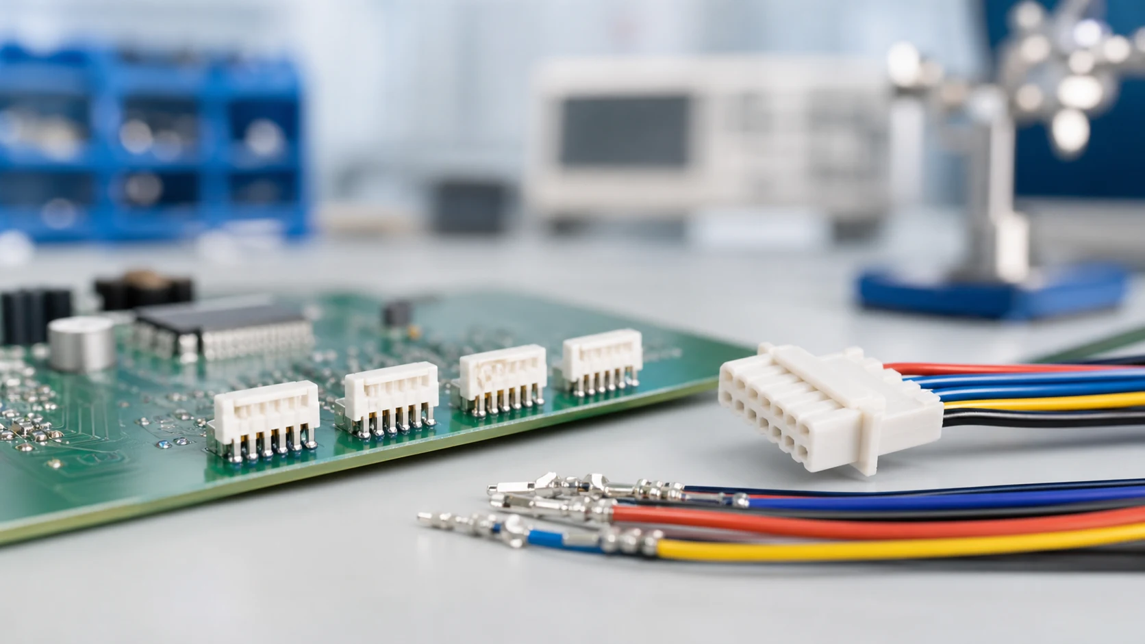
In common usage the wafer is the board-mounted header whose contacts mate with a wire-side housing carrying crimped terminals. It converts board circuits into a serviceable wire interface for internal power, signal and sensor runs. For a related technical reference, see Pin Header vs Socket Header: When Each Board Connection Makes Sense.
| System element |
Key decisions |
Failure risk if skipped |
| Board header |
Pitch, orientation, solder interface |
Layout rework or weak joints |
| Wire housing |
Circuit map, locking, polarization |
Back-out or mis-mating |
| Crimped terminals |
Wire range, tooling, inspection |
Unstable contact resistance |
Treat the description “wafer” as a starting point for identification, not a controlled mating specification. Equal pitch and position count do not establish matching pin dimensions, contact engagement, shroud geometry, polarization or latch position. A photograph can help locate a family, but the release package should identify header, housing and terminal part numbers and drawing revisions, with supplier confirmation that those exact parts are intended to mate.
A complete wafer connector inquiry also distinguishes an assembled harness from loose components. State who supplies and approves the crimped wire side, whether secondary locks are included, and whether an alternative supplier is proposed. An alternate needs its own documented compatibility and validation review; “same pitch” is not an interchangeability statement.
Start from circuit count, current and voltage per circuit, wire sizes, mating orientation and available board space. Add environment, service expectations and the assembly method, because those inputs later decide locking, plating and pitch.
Does the connector fit after the harness and enclosure are installed?
Board footprint is only one part of the mechanical envelope. Check the mated height and width, the travel needed to insert and withdraw the housing, access to the latch, and clearance for a finger or the specified service tool. Then check the wire exit, bend space and routing to the first support against the cable supplier’s requirements. A right-angle header may reduce height yet move the withdrawal path into an enclosure wall.
Review access in the equipment’s actual service state, with adjacent components and the harness installed, rather than on a bare board. Establish how the housing is held during removal without pulling the wires or levering against solder joints. Confirm whether terminal extraction is permitted, which tool is specified, and whether damaged retention parts must be replaced. There is no universal service-clearance dimension: use the selected connector drawings and a representative enclosure check.
Which operating conditions should accompany the circuit map?
Record simultaneous loads, duty cycle, local ambient temperature, nearby heat sources and expected cable movement. Identify moisture or chemical exposure only where it is credible for the equipment. If a sealing or environmental performance claim is necessary, request evidence for the specified assembly rather than inferring it from an enclosed location or housing material name. These inputs let the supplier identify gaps before a sample is mistaken for an approved solution.
How should pitch, circuit count and current be evaluated together?
Finer pitch can shrink the footprint, but contact dimensions and thermal behaviour depend on the family rather than pitch alone. Higher-current circuits may need a different contact system, coarser pitch or a supplier-approved loading arrangement. Confirm the combination with a temperature-rise review under the real load pattern rather than a single-contact figure.
Ask which wire, number of loaded circuits and ambient conditions support the published rating, then compare those conditions with the proposed assembly. A headline current value does not answer whether all positions can carry that load simultaneously in a warm enclosure. Do not assume unused positions, parallel contacts or a larger conductor automatically increase the allowable load; any such arrangement needs approval and representative verification.
Separate spacing from voltage suitability as well. Pitch alone does not establish the insulation performance of the complete housing, board layout and installed assembly. Request the applicable product specification and equipment-level requirements. The test-selection principle in IEC 60512-1:2018 is useful here: the detail product specification must prescribe tests, severities and permissible performance limits, not merely name a standards series.
What is the difference between connector locking and terminal retention?
Friction-only interfaces can be compact, but their suitability under vibration and cable loads needs verification; positive locks add a defined engagement and removal action. Match the retention style to vibration exposure and to how often service will disconnect the interface. For a related technical reference, see Wafer Connector vs FFC/FPC Connector: Selecting for Vibration and Service Access.
| Retention style |
Behaviour in service |
Typical fit to evaluate |
| Friction only |
Compact, no separate latch-release action |
Protected, low-vibration locations, subject to load verification |
| Positive lock |
Defined engagement and release |
Vibration exposure or repeated service, if access and cycle requirements are met |
| Lock plus strain relief |
Reduces load transmitted to contacts when correctly implemented |
Cable movement near the interface |
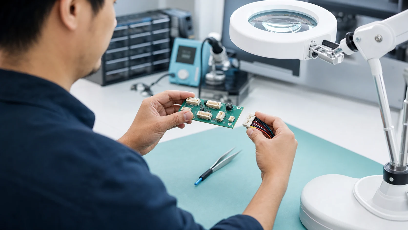
The housing-to-header lock and terminal-to-housing retention solve different problems. A visibly engaged connector latch does not prove that every terminal is seated. A terminal can move inside a locked housing if its primary retention feature is damaged or not engaged. Molex’s connector contact retention discussion distinguishes connector-level locks and connector position assurance from terminal lances and terminal position assurance (TPA). It also shows that TPA implementations vary by family; the presence, function and installation sequence must be checked for the selected design.
Specify how full mating and terminal seating will be inspected, and route the harness so cable movement is managed by suitable support rather than the latch alone. Do not apply an improvised production tug test: its load and direction could damage a small terminal. Use the supplier-approved verification method and limits. Connector withdrawal force, terminal retention and crimp pull strength are separate measurements, not interchangeable labels for one test.
How should terminals, wire insulation and crimp tooling be controlled?
Crimp quality lives in tooling, wire preparation and process monitoring, and it influences the interface’s electrical stability. Require the terminal-to-wire combination, tooling references and inspection criteria to be documented in the build package.
Conductor size is not a complete wire specification. Record conductor construction and the insulation material and outside diameter for the exact wire part. Two wires with the same nominal conductor size can fit the insulation support differently. Verify both the conductor crimp and insulation support against the terminal application specification; neither a generic AWG match nor a terminal that enters the housing establishes an acceptable termination.
The controlled build package should identify the terminal revision, wire part, approved applicator or hand tool, die set and applicable setup. Obtain strip-length and crimp-dimension requirements from the selected combination’s instructions. Define inspection, crimp pull-test sampling where required, tool maintenance and record retention through the agreed control plan. These are procurement and process-control recommendations, not universal dimensions or test limits.
For an example of the documentation separation, TE Connectivity contact 2415838-1 is a crimp receptacle contact terminating to wire and cable. Its official page separately lists product drawing 2415838 Rev A, application specification 114-106638 Rev B and product specification 108-106638 Rev A. This example shows which documents to request; it is not a ZUCH mating approval, PCB-header rating or source of transferable crimp settings.
Wichtig: General guidance cannot approve a specific design or lot. The IPC Standards Revision Table lists IPC/WHMA-A-620, Requirements and Acceptance for Cable and Wire Harness Assemblies, at Rev F, October 2025. The public catalogue verifies the document identity and revision, not its detailed acceptance thresholds. Agree the applicable revision and acceptance requirements, obtain the necessary standard, and apply it together with controlled supplier instructions and the programme’s acceptance plan.
What proves the assembly is ready for release, and when is retesting needed?
Validate representative assemblies for mating behaviour, retention, electrical stability and any environmental exposures the design claims. Name samples, methods, limits and records, and define which changes reopen the validation.
Why is continuity not enough to approve the connection?
A continuity check can confirm the circuit map and detect opens or shorts under its test conditions. It does not establish terminal retention, conductor-crimp strength, latch security or allowable temperature rise. A partially seated contact may touch during a static test without remaining stable under movement. Separate production electrical screening from mechanical and environmental qualification, and record which claim each test supports.
| Verification task |
Question it addresses |
Required release information |
| Continuity and circuit-map screening |
Are the intended circuits connected without unintended connections? |
Test conditions, fixture map and agreed electrical limits |
| Terminal seating, retention and crimp verification |
Are the terminal and wire mechanically secured as specified? |
Separate methods, load directions, limits and sampling for each feature |
| Mating, locking and service-access checks |
Can the installed pair engage, remain secured and be released correctly? |
Actual enclosure and harness, removal method and required service cycles |
| Thermal and relevant environmental qualification |
Does the selected assembly meet performance limits under its intended loads and exposures? |
Representative loading, ambient, exposure severity and before/after measurements |
IEC 60512-1:2018 provides a framework for connector tests and measurements, while the detail product specification selects the tests, severity and permissible performance limits. Citing the standard alone is neither certification nor a complete qualification plan. Confirm which records cover the exact mating pair, wire, tooling and operating configuration; evidence for a contact or component alone may not cover the installed system.
Which changes should trigger targeted retesting?
Use a risk-based change review rather than automatically repeating every test or accepting a supplier’s “equivalent” label. Identify the changed feature, the failure mechanisms it can affect, the existing evidence that remains applicable, and the additional verification needed before release. The responsible engineering and quality owners should document the rationale and approval.
- A wire construction or insulation change calls for a terminal-application review and reassessment of crimping, insulation support and routing.
- A terminal, plating, housing or latch revision calls for review of the affected mating, retention, electrical or environmental evidence.
- A tooling, applicator, setup or assembly-location change calls for confirmation that the controlled process still produces the specified termination.
- A higher load, hotter enclosure or different harness support calls for review of the affected thermal or mechanical validation.
For a higher-consequence circuit, unresolved compatibility or limited original evidence may justify broader requalification. A documented change that does not affect a verified function may need a narrower confirmation. Neither decision should rely solely on a continuity pass, and no fixed retest frequency is implied here.
What should a complete ZUCH wafer connector RFQ contain?
Use ZUCH’s Small Pitch Connectors category and the live product catalogue to identify relevant connector, terminal or housing component families. These are discovery routes only and do not demonstrate that a specific configuration is approved for your application.
Which details turn a pitch-only request into a mating-pair RFQ?
- Identify the board header, mating housing, crimp terminal and any secondary lock by part number and drawing revision; request confirmation of the intended pair.
- Provide the circuit map with current, voltage and exact wire part per position, including conductor construction and insulation outside diameter.
- State pitch, orientation, solder interface, locking and polarization requirements, plus the installed service-access envelope and harness supports.
- Request crimp tooling references, application instructions, inspection criteria and records; identify who assembles and controls the wire side.
- Define validation scope, representative samples, approved methods, limits and change triggers, and identify any proposed alternates separately.
A useful supplier response should distinguish confirmed information from open items. Missing wire approval, mating confirmation or test conditions should remain an engineering action, not disappear into a generic quotation description. Compare total sourcing effort as well as unit price: additional tooling, inspections, harness assembly and layout changes can materially change the buying decision, but their cost must come from the actual programme rather than an assumed saving.
What remains outside the scope of this guide?
This guide supports engineering and sourcing discussion; it cannot replace programme-specific validation, market requirements, or an approval record. Use ZUCH’s sample request route or contact page for controlled component documentation and samples.

Frequently asked questions
What is a wafer connector?
In common board-to-wire usage, it is a board-mounted header that mates with a housing containing crimped wire terminals. The term alone does not specify the mating housing or terminal, so use controlled part numbers and drawings for purchasing.
Where are wafer connectors typically used?
They connect board circuits to wired subassemblies inside equipment, such as sensors, fans, panels and internal power runs. Suitability still depends on the specific electrical load, environment, harness routing and servicing requirements; the application category is not approval evidence.
How do I choose the pitch for a wafer interface?
Balance footprint limits against the selected family’s contact system, current per circuit and assembly capability, then verify thermal behaviour with the real load pattern. Equal pitch between two products does not prove they mate, so confirm the complete pair before freezing the board layout.
Do wafer connectors need a locking feature?
Not always; the decision depends on mechanical loads, handling, environment and the consequences of disconnection. A positive lock does not replace terminal retention or strain relief. Confirm that the latch can be reached and released in the installed equipment and validate the selected arrangement.
Why does crimp quality matter so much here?
The crimp influences both wire retention and electrical stability, and a static continuity pass cannot establish either across service conditions. Control the exact terminal, conductor, insulation diameter and tooling combination. Obtain crimp requirements and acceptance limits from the applicable instructions rather than copying settings from another family.
Can one wafer family cover both signal and power circuits?
Sometimes, if the family’s approved contact arrangements and the circuit requirements support it. Confirm the permitted loading and wire combinations, then review electrical and thermal performance for the actual assembly. Do not assume mixed contacts or parallel positions are available or approved without supplier documentation.
What should a wafer connector RFQ contain?
Include the complete header-housing-terminal pair, circuit map, exact wire details, mechanical and locking requirements, crimp documentation, validation plan and required records. State the service envelope and who assembles the harness. A request containing only pitch and circuit count is an identification inquiry, not a release-ready specification.
References
Public sources checked on October 10, 2026. The standards catalogue summaries establish scope and document identity, not detailed acceptance thresholds; manufacturer examples do not qualify ZUCH products.
When is the mating pair ready to approve?
Approve a wafer connection as a documented mating system, not as a pitch measurement or a header purchased in isolation. First identify the header, housing, terminals and wires; then confirm the application instructions, tooling and installed service envelope. Next compare the real circuit loading and environment with the evidence for that configuration, and close the gaps through an agreed validation plan. Do not let a successful continuity check substitute for terminal retention, crimp verification or mechanical qualification. After release, assess changes by the functions they can affect and retain the rationale for targeted retesting. ZUCH’s product catalogue and sample-request routes provide a starting point for obtaining component documentation and discussing a defined RFQ; approval remains tied to the selected assembly and its controlled requirements.
 Zhejiang ZUCH Technology Co., Ltd.