Male Tab Terminals: How Tab Width and Thickness Affect Mating Performance
A female receptacle can be the right nominal width and still fit a male tab too loosely or require excessive force. Thickness, lead-in geometry and the actual contact design determine whether the pair can be used. This guide explains those dimensions separately, including a documented case where one specific receptacle accepts two thicknesses. It also gives a practical inspection sequence for an interface that does not mate as expected.
The short answer is to specify male tab terminal width and thickness together with the approved mating receptacle. A size-series label is not a tolerance, a current rating or permission to mix parts. The drawing and application specification determine the acceptable pair.
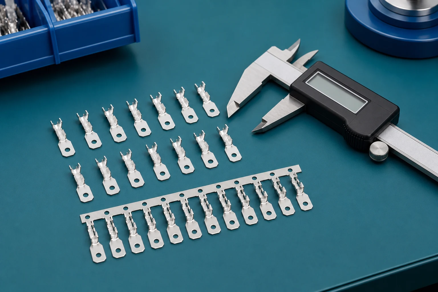
Contents
What does a male tab terminal need to mate correctly?
A male tab terminal is defined by more than its nominal tab width. The mating pair needs a controlled interface: tab geometry, thickness, material and finish, female-contact design, housing alignment, and the actual operating environment. Start with the drawing and the mating contact specification rather than a catalogue photograph.
| Review area |
Control question |
Why it matters |
| Matched interface |
Which terminal, mate, and housing are specified? |
Prevents a nominal-size assumption from becoming a release decision |
| Application envelope |
What are the routing, environment, and handling conditions? |
Reveals loads that a static component comparison misses |
| Acceptance evidence |
Which inspection or validation evidence is required? |
Aligns engineering and sourcing expectations |
Width establishes the contact family and the lateral position of the female receptacle on the blade. A near-looking tab can still be unsuitable when its measured width, edge shape, or shoulder geometry differs from the specified interface. Record the nominal dimension, tolerance, and the referenced mating contact before requesting a component proposal.
How does tab thickness affect contact force and insertion?
Thickness affects how far the female contact spring is deflected during mating. Too little thickness can reduce intended contact engagement; too much can increase insertion force or overstress the receptacle. Neither outcome can be judged from a generic terminal size label, so use the controlled pair and the required test method for the application.
Which tab dimensions are often missed in an RFQ?
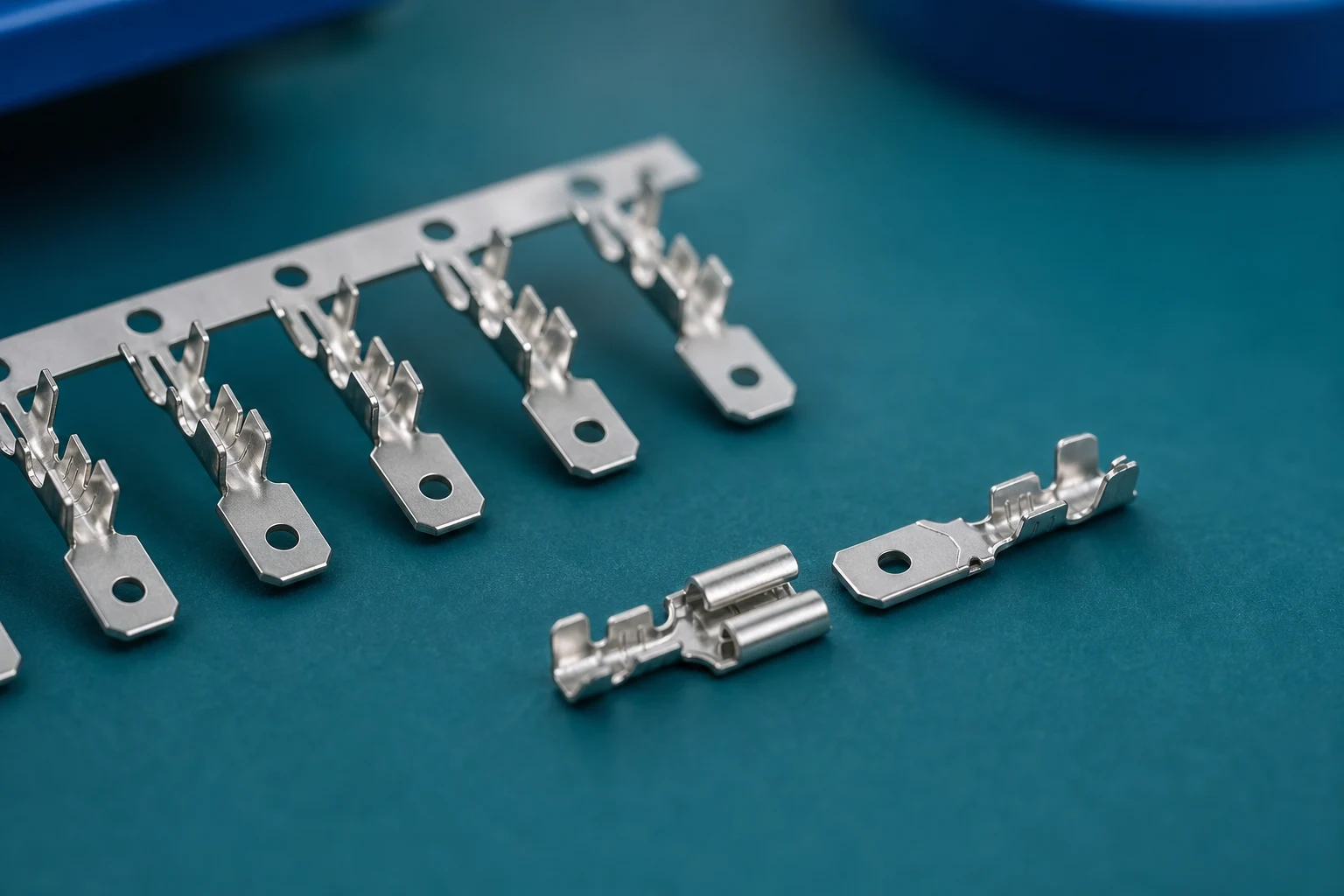
Include the blade length, lead-in, edge condition, shoulder location, stop feature, and terminal orientation. These details influence insertion, contact seating, housing retention, and the available clearance around the connection. Also state whether the part mates before or after it enters a housing, because the assembly sequence may impose additional limits. The female terminal retention features must also allow the contact to reach and remain in its intended housing position.
| RFQ input |
What to state |
Decision supported |
| Component set |
Terminal, mate, housing, and orientation |
Interface compatibility review |
| Geometry |
Controlled dimensions and clearances |
Insertion and engagement review |
| Application |
Wire, routing, environment, and service conditions |
Retention and protection review |
| Evidence |
Samples, inspection, and acceptance plan |
Programme release review |
How should plating be matched to the operating environment?
Plating, base material, and the surrounding environment should be evaluated as an interface system. The correct choice depends on the specified female contact, expected exposure, current path, vibration, enclosure, and any programme requirement. Avoid treating a plating name as evidence that the completed connection is approved for every condition. For a moving harness, assess spade terminal behaviour in vibration using the complete terminal and wire assembly rather than the plating name alone.
IEC 61210:2010 addresses defined non-insulated flat quick-connect terminations for electrical copper conductors, including dimensional and performance requirements. Its scope is not a claim that every blade-style terminal or every conductor material is covered. Check the selected product and the equipment requirements.
What evidence is needed before a terminal is approved?
Ask for a controlled part definition, mating-contact reference, application dimensions, and the validation or acceptance evidence required by the programme. Inspection should also address terminal orientation, damage, seating, and any condition that could prevent the receptacle from reaching its intended position.
What should a supplier receive to propose a suitable terminal?
ZUCH’s connecting terminals provide a starting point for a component inquiry. Send the male tab and receptacle references together so the proposal can address the actual interface rather than a nominal width alone.
Which records should accompany the terminal RFQ?
- Controlled terminal, mating contact, and housing references.
- Drawing revision, dimensions, wire definition, and assembly orientation.
- Routing, environment, service, and mechanical constraints.
- Required samples, inspection or validation evidence, acceptance criteria, and records.
- Change-control and nonconformance expectations.
What can terminal samples confirm before production?
Define what the terminal samples will be checked for: geometry, insertion, seating and any agreed electrical or environmental evaluation. A sample that fits once does not establish the finished harness’s service life or programme approval.
Can a 187-series receptacle accept both 0.5 mm and 0.8 mm tabs?
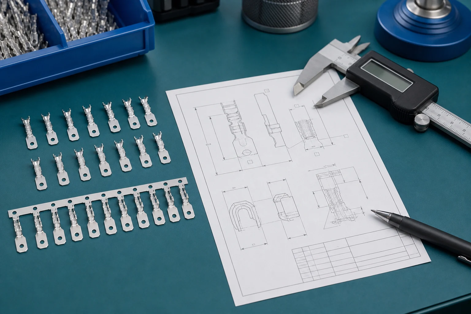
Sometimes, but only for a part designed and documented for both. TE Connectivity’s FASTON page identifies a specific 4.8 mm (187) multi-thickness receptacle for 0.5 mm (.020 in) or 0.8 mm (.031 in) tabs. That is a useful exception to know, not a rule for every 187-series receptacle. Specify the exact female part before accepting either thickness.
Retain the manufacturer’s nominal dimensions and tolerances when comparing quotations. A metric label and a rounded inch-series name can describe the same family without being the same drawing limit. Do not replace the controlled tolerance with a rounded unit conversion, and do not infer current capacity from the width-series number.
What should be checked when the terminal pair feels too tight or loose?
| Observed symptom |
First checks |
Action boundary |
| Excessive insertion force |
Approved tab thickness, width, lead-in, damage and alignment |
Do not force a mismatched part or file the blade to make it fit |
| Unexpectedly loose fit |
Receptacle thickness range, contact deformation and previous use |
Do not bend the contact spring as an unapproved repair |
| Contact does not fully seat |
Blade length, stop features, housing position and retention |
Resolve the obstruction before electrical release |
| Fit is acceptable but heating occurs |
Loaded configuration, conductor, crimp, interface condition and test limits |
Do not assume a wider tab alone will correct the fault |
This sequence is a proposed diagnostic checklist, not a report of measured insertion forces or a field-failure rate. Record the actual parts and inspection result, then follow the supplier’s acceptance criteria. IEC 60512-1:2018 provides the framework for connector testing with detail specifications; it does not supply one universal acceptance force for every tab.
If the connection also falls within the safety scope of IEC 61984:2008, identify the applicable requirements with the equipment design. A connector standard title does not establish approval for an unspecified terminal pair.
Preguntas frecuentes
Does a 250-series terminal label specify the tab thickness?
No. A width-series designation is not a complete dimensional specification. Obtain the actual male-tab drawing and the female receptacle's allowed thickness range, tolerances, lead-in and engagement dimensions before selecting the pair.
Can a 187 receptacle accept both 0.5 mm and 0.8 mm tabs?
Only if that exact receptacle is specified for both. TE documents a particular 4.8 mm (187) multi-thickness FASTON design for those thicknesses. Do not extend that capability to every receptacle carrying the 187-series label.
Does a wider male tab terminal always carry more current?
No. Current capability belongs to the complete connection under specified conditions. Conductor size, crimp quality, contact design, temperature, housing and loading all matter. A width label alone cannot provide a current rating.
Why can a correct-width female receptacle still feel loose?
Its permitted tab thickness may differ, or the spring contact may be damaged or worn. Compare the exact pair and inspect its condition. Do not compensate by bending the receptacle unless the manufacturer explicitly specifies an approved procedure.
Can metric and inch terminal-size labels be compared directly?
Use the supplier's controlled drawing, not the rounded family label, for acceptance. Preserve nominal dimensions, tolerances and the stated unit system. A familiar inch-series designation is not a substitute for the exact metric or inch mating limits.
What evidence should accompany approval of a male tab terminal?
Keep the male tab, receptacle and housing references, drawing revisions, wire and crimp details, required force or retention checks, electrical conditions and relevant test results together. A photograph or a single successful insertion cannot establish the approved application.
Conclusion
Male tab compatibility depends on the complete mating interface, not on width alone. Start with the female receptacle specification and confirm the male tab’s width, thickness, tolerances and engagement geometry. Keep documented multi-thickness designs separate from ordinary single-range receptacles, and preserve controlled dimensions when comparing metric and inch labels. If a sample is too tight, loose or difficult to seat, inspect the pair and assembly rather than modifying a contact to make it fit. Electrical suitability still needs the intended conductor, load and acceptance evidence. ZUCH can be approached with the matched-part references and drawings, allowing the inquiry to focus on a defined terminal configuration instead of a generic size designation.
 Zhejiang ZUCH Technology Co., Ltd.