Zhejiang ZUCH Technology Co., Ltd.
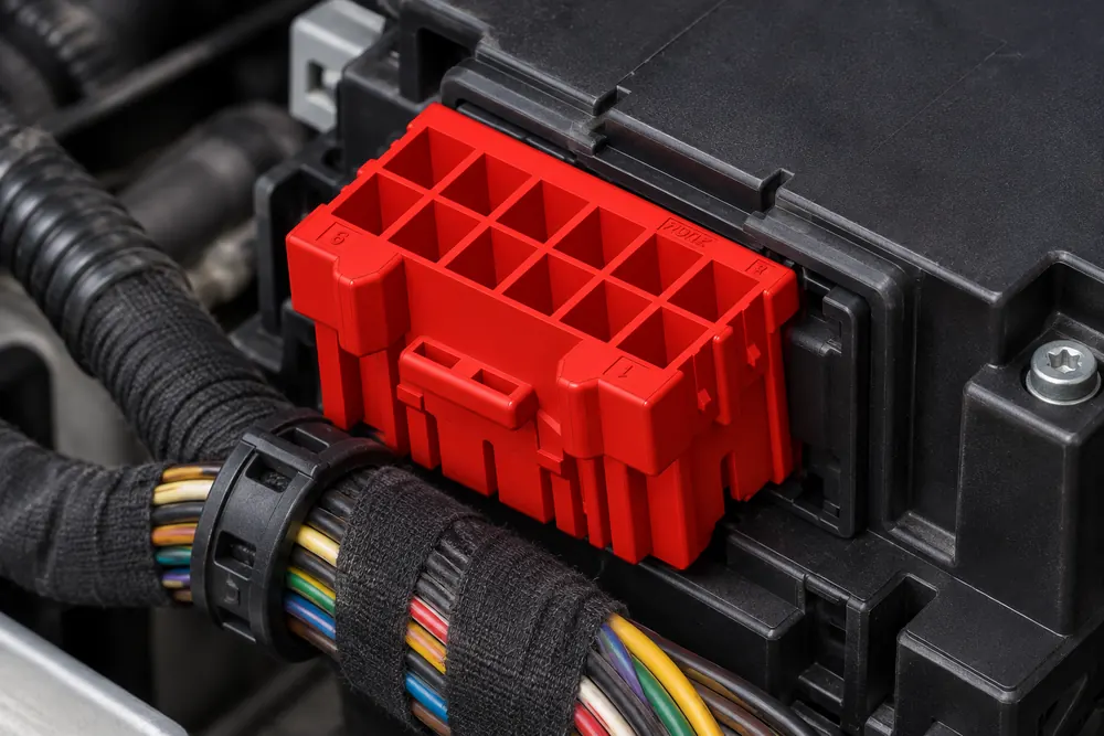
When a body-electronics engineer in Nagoya connected a fifteen-circuit harness for a new tailgate module, the connector latched but two status signals were reversed; the visible failure appeared in software, while the root cause was an unverified pinout and mating-housing reference.
Resumen: A 15-pin automotive connector is used to carry a defined group of power, ground, sensor, actuator, and communication circuits between a vehicle harness and a module. Fifteen cavities do not imply a universal pin assignment: identify every circuit from the vehicle drawing, match the exact keyed housing and terminal family, and verify continuity and retention before production. SAE USCAR-2 provides automotive connector-system performance context, while IEC 61984 addresses connector safety requirements and tests. Approve a mated sample and controlled pinout—not a similar-looking shell—before buying volume.
Fifteen positions are useful when a body controller, door, seat, lighting, infotainment, or sensor assembly needs more circuits than a small connector can provide but still benefits from one compact interface. The connector organizes power and signal paths, supports a serviceable harness, and limits assembly errors when cavity identification, keying, and terminal selection are controlled.
What should a fifteen-circuit pinout prove before sourcing?
Start with the function of the module and list the circuits it must exchange. Typical assignments include battery or ignition feeds, multiple grounds, lamp outputs, switch inputs, sensor references, LIN or CAN communication, and diagnostic lines. A pinout reference should show cavity number, circuit name, wire color or ID, expected voltage, direction, and any shielding or twisted-pair requirement.
Use the connector drawing’s mating-face view and wire-entry view consistently; reversing the view is a common cause of swapped circuits. Mark populated and spare cavities separately, and identify any high-current position that uses a different terminal size. The 15-pin power connector design overview offers useful cross-industry context, but the vehicle OEM pinout remains authoritative.
| Pinout field | Example information to capture | Control achieved |
|---|---|---|
| Cavity identifier | Number, view orientation, key position, populated/spare status | Prevents mirrored numbering and unintentional circuit swaps |
| Electrical role | Feed, ground, sensor, actuator, LIN/CAN, diagnostic | Separates load paths from low-level signals |
| Operating limits | Nominal voltage, continuous/inrush current, duty cycle, temperature | Supports terminal, wire, fuse, and derating decisions |
| Termination data | Terminal part, plating, wire range, crimp and seal reference | Creates a repeatable harness build and repair record |
Confirm the pinout with a continuity test on a de-energized sample, then perform a controlled power-up according to the vehicle or module procedure. Continuity proves a path; it does not prove that a terminal is fully seated, that a CAN pair is correctly oriented, or that a housing will remain locked under vibration.
Why housings, keying, terminals, and locks must be approved as one system
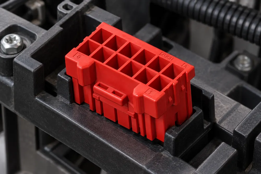
For a reliable 15 pin automotive connector, specify the plug, receptacle, terminal, seal, secondary lock, and connector-position assurance feature together. “Male” and “female” descriptions can be ambiguous because the contact and the housing may use different gender conventions. Part-number mating tables and a physical sample remove that ambiguity.
Check polarization ribs, key codes, latch location, terminal orientation, cavity plugs, and cable-exit direction. Two fifteen-position housings can share an outline yet use different keys, pitch, contact sizes, or lock positions. SAE USCAR-2 evaluates connector systems through attributes such as retention, mating durability, and environmental performance; a photograph cannot establish those attributes.
| System element | Questions for engineering and purchasing | Risk when overlooked |
|---|---|---|
| Mating housings | Are both exact part numbers approved, keyed, and available in the required orientation? | Incomplete mating, wrong circuit alignment, or assembly-line stoppage |
| Terminal family | Does each cavity use the specified contact size, plating, and wire range? | High resistance, heat rise, weak retention, or intermittent signals |
| Locks and seals | Are CPA/TPA features, cavity plugs, grommets, and backshells compatible? | Terminal back-out, water ingress, and difficult service |
| Mechanical envelope | Do panel clearance, bend radius, strain relief, and latch access meet the installation? | Harness stress, connector damage, or inaccessible repair points |
Use a go/no-go mating check and verify that the secondary lock reaches its final position only when all terminals are seated. For critical signals, add a terminal-retention check and inspect crimp height or pull force according to the terminal maker’s work instruction.
For procurement, ask whether the connector uses terminal-position assurance, connector-position assurance, or both. TPA helps reveal and resist terminal back-out, while CPA helps confirm the mated pair stays locked. Neither feature replaces a correct terminal family, wire range, seal diameter, and controlled crimp.
How sealing, wire gauge, and serviceability change by vehicle location
Choose an unsealed housing for a protected cabin or module location only when the vehicle specification allows it. Engine-bay, wheel-well, underbody, and exterior interfaces generally require a sealed system with the correct wire seals, cavity plugs, and strain relief. The automotive connectors and terminals guide explains why the contact and housing must be treated as one application.
Wire gauge follows current, voltage drop, temperature, bundle derating, and termination limits—not pin count. A fifteen-position housing may combine small signal terminals with larger power contacts. Specify wire insulation diameter so seals grip correctly, and avoid substituting a terminal whose crimp barrel or locking lance does not match the cavity.
Plan service before launch. If a field technician may replace one circuit, confirm approved extraction tools, replacement terminals, seals, and inspection criteria. A terminal that has been over-crimped, bent, or released with an improvised pick may no longer meet retention requirements. Replace the affected component when the service procedure calls for it rather than forcing a repair.
What validation evidence separates a fit check from production approval?
Validation should progress from document review to sample testing. Check the pinout, mating cycle, terminal retention, crimp quality, contact resistance, insulation resistance where applicable, thermal exposure, vibration, and ingress condition. IEC 61984 is a safety and test reference for connectors; it is not an automatic certification of a complete vehicle harness. Test levels and acceptance criteria still come from the application and customer specification.
SAE USCAR-2 can guide an automotive connector performance conversation, while NHTSA’s vehicle-safety resources provide US regulatory context. Neither source should be used to imply that a particular connector is approved for every vehicle. Applicability depends on destination market, intended use, vehicle-maker requirements, and the claims made in product literature.
Include the cost of terminals, seals, applicators, crimp validation, testing, repair kits, minimum order quantities, engineering changes, and potential rework. A low unit price can become expensive if a connector causes a harness line stop or a field campaign. Controlled drawings, traceable samples, and change notification reduce those hidden costs.
What should the supplier receive before recommending a 15-pin connector?
- Freeze the interface: record the vehicle-side connector, mating part, key code, cavity view, and installation envelope.
- Create the circuit matrix: assign all fifteen positions with electrical role, current, wire, signal, and spare status.
- Choose the system: match housings, terminals, seals, locks, strain relief, and service tools as a family.
- Approve evidence: review drawings, material declarations, crimp instructions, test data, and change-control terms.
- Validate samples: run mating, continuity, retention, environmental, and repair checks required by the application.
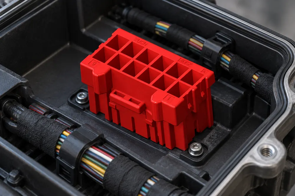
ZUCH can support sourcing teams evaluating a configurable 15 pin automotive connector for body, lighting, control, and sensor harnesses. Provide the pinout, mating reference, environment, annual volume, and documentation requirements so options can be screened on fitment and evidence rather than on cavity count alone.
Preguntas frecuentes
What is a 15-pin automotive connector typically used for in multi-circuit body and control wiring?
It connects a grouped set of up to fifteen circuits between a body, lighting, seat, door, sensor, or control module and its wiring harness. Positions can carry power, grounds, actuator outputs, switch inputs, and communication lines. The actual assignment is vehicle-specific, so use the approved pinout rather than a generic chart.
How do I confirm that a 15-pin automotive connector matches my vehicle wiring?
Match the vehicle-side and mating part numbers, keying, cavity numbering view, terminal family, wire range, and seal arrangement against an OEM or supplier drawing. Test a sample for latch engagement, terminal seating, continuity, and the environmental conditions required at its location. A shared fifteen-position count is not proof of compatibility.
Do 15-pin automotive connectors need a matching male and female housing?
Yes, the mated interface needs the specified plug and receptacle or approved board/header counterpart, with compatible contacts and locks. Gender labels vary between families, so rely on mating tables and part numbers. Never force two housings together because their cavity count and outside shape appear similar.
What terminal and wire-gauge options are common for a 15-pin automotive connector?
Fifteen-position housings may use small signal contacts, larger power contacts, or a controlled mix where the family permits it. Tin-plated copper-alloy terminals are common, while other finishes may suit corrosion or low-level signal requirements. Select wire gauge from the terminal’s crimp range, current and temperature limits, voltage drop, and seal diameter.
When should I choose a sealed 15-pin automotive connector?
Choose a sealed system for splash, dust, salt, condensation, or engine-bay and exterior exposure, and validate the complete mated assembly. Confirm that wire seals, cavity plugs, backshell, and strain relief match the selected terminal family. An unsealed connector can be appropriate in a protected cabin when the vehicle specification permits it.
Can I replace one terminal in a 15-pin connector without replacing the full housing?
Often this is possible when the housing is serviceable and the replacement terminal, seal, and extraction tool are approved. Inspect the cavity, retention lance, secondary lock, wire crimp, and seal after removal; replace damaged parts according to the service procedure. Do not insert a visually similar terminal that has not been validated for the housing.
Sources for 15-pin connector application and validation decisions
- SAE USCAR-2: Performance Specification for Automotive Electrical Connector Systems
- IEC 61984: Connectors — Safety requirements and tests
- National Highway Traffic Safety Administration: Vehicle Safety
The reliable principle is simple: fifteen cavities organize a harness, but only a verified pinout, matched terminal system, and tested mated interface make it dependable.
For a documented 15 pin automotive connector option, review ZUCH products and contact the team with your circuit matrix, mating connector, environment, and validation needs.