Zhejiang ZUCH Technology Co., Ltd.
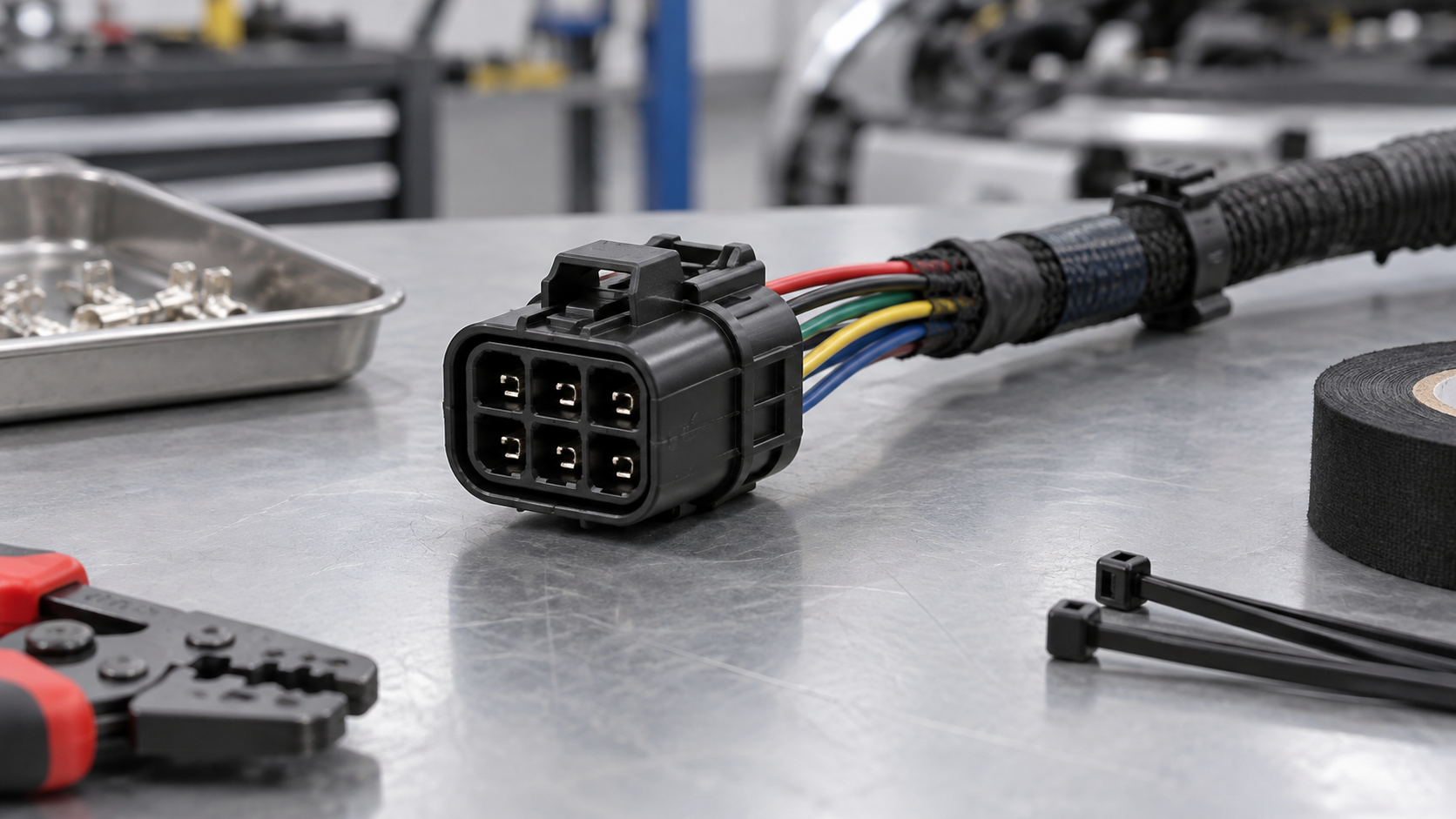
When a harness engineer in Detroit encounters a six-circuit replacement before a vehicle build, the connector may appear to fit the mating half, yet the first continuity check can fail because the cavity view was mirrored and the terminal family was different. The visible failure is not necessarily a bad connector; it can come from selection, specification, or assembly controls. A 6-pin automotive electrical connector must be matched as a complete interface: housing, keying, terminals, wire range, seals, locks, circuit map, and operating environment. This guide gives engineering and procurement teams a repeatable way to identify the right part, compare alternatives, and define the evidence required before production approval.
Resumen: A six-pin label describes position count, not a universal fit. Confirm the mating housing and key code, cavity numbering view, terminal geometry, conductor size, current and voltage per circuit, sealing architecture, temperature and vibration exposure, and service method. ISO 8092 covers road-vehicle low-voltage harness connections, while SAE USCAR-2 provides a performance framework for automotive connection systems; neither makes visually similar parts interchangeable. The next action is to freeze the pin map and request a controlled drawing, mating sample, terminal data, and validation plan before placing a volume order.
Why does a six-position label fail to prove compatibility?
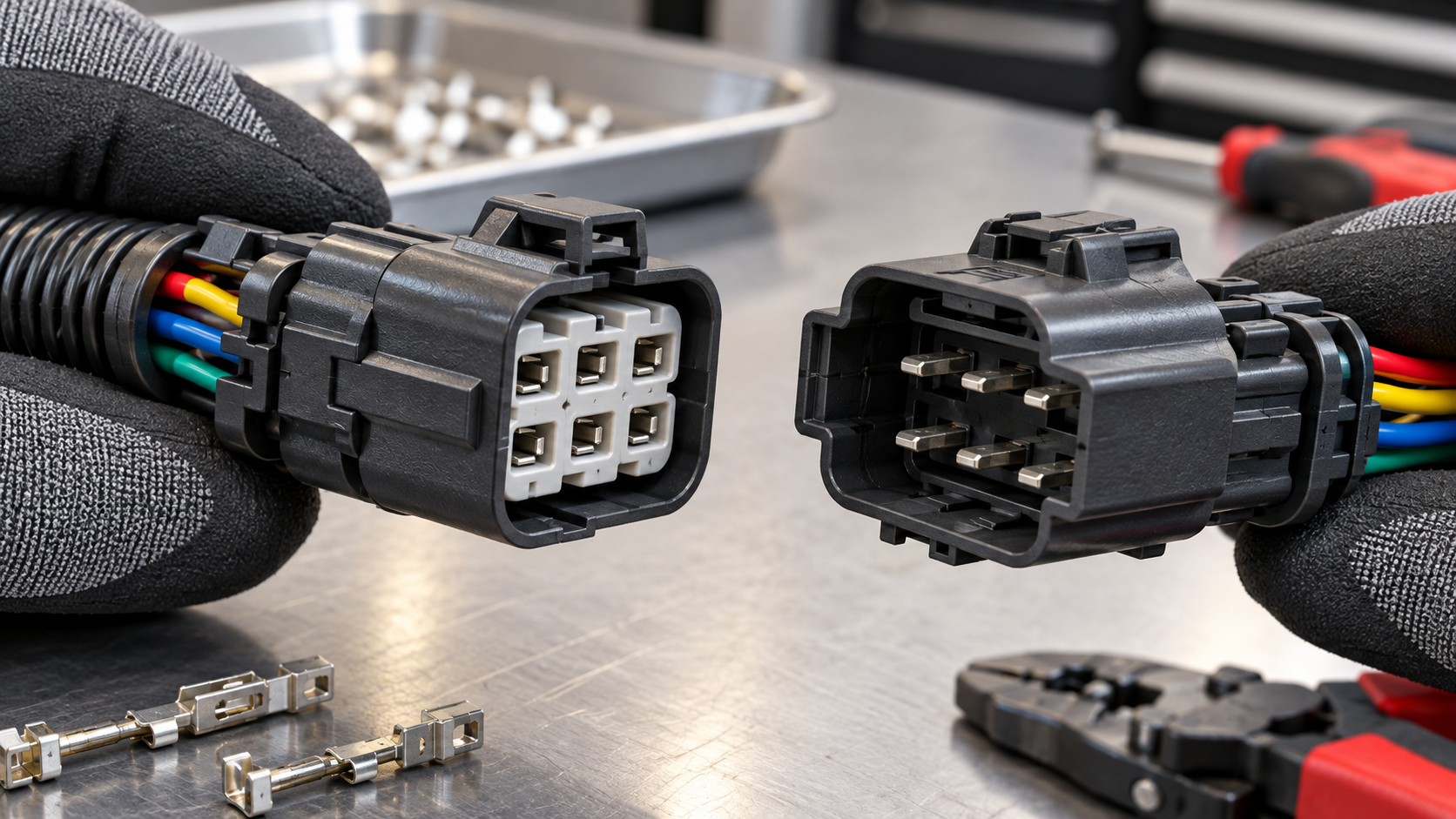
A six-position housing can carry very different circuit mixes: power and ground, sensor reference and signal, actuator controls, communication lines, or spare cavities. Two housings with the same count may use different row spacing, polarization, latch location, terminal gender, and cavity numbering. A drawing or service document must define whether the view is the mating face or wire side; otherwise the harness can be mirrored during assembly.
Start with the existing mating part and record its manufacturer, family, part number, keying, mounting feature, and terminal system. Photograph both faces, mark cavity 1, and note populated and unused positions. The public automotive connector identification guide can help organize this evidence, but the vehicle or equipment drawing remains the controlling source.
Which electrical and mechanical inputs should the RFQ include?
Define each circuit rather than assigning one generic rating to the complete housing. Record nominal voltage, continuous and inrush current, switching or signal duty, wire conductor area, insulation diameter, and expected temperature. A six-cavity connector may require more than one terminal size; the approved wire range and crimp tooling belong to the terminal part number, not the cavity count.
Also state the mechanical and environmental conditions: mating direction, retention and secondary-lock features, vibration, fluid exposure, dust, condensation, salt, service access, and required mating cycles. For a sealed system, specify cavity seals, perimeter gaskets, cavity plugs, backshell, and strain relief together. An enclosure-level ingress claim cannot compensate for a nicked wire seal or an incompletely latched secondary lock.
How should engineers compare six-pin connector options?
| Dimension | Option A: protected unsealed interface | Option B: sealed interface | Evidence to request |
|---|---|---|---|
| Environment | Suitable only where the enclosure controls moisture and contamination | Designed for specified splash, dust, or fluid exposure when correctly terminated | Application exposure definition and assembly drawing |
| Terminal system | May simplify access and replacement in a dry cabin location | Requires compatible wire seals, cavity plugs, and seal tooling | Terminal datasheet, wire range, crimp specification |
| Fit and keying | Still requires exact mating half, polarization, latch, and cavity map | Same fit requirements plus seal compression and backshell clearance | 2D drawing, face view, mating sample, key code |
| Serviceability | Often easier to inspect and depin if the location is accessible | Needs approved depinning, seal replacement, and revalidation steps | Service procedure and replacement-parts list |
| Total cost | Lower part complexity can reduce assembly effort where exposure is controlled | Additional parts and process controls can reduce moisture-related rework | Illustrative cost model including labor, inspection, and returns |
The table is a decision framework, not a performance claim for any unlisted part. Compare candidates under the same circuit load, wire, tooling, and environmental profile; a catalog photograph cannot establish equivalent performance.
How do cavity map, wire size, and terminal retention work together?
Build a six-row circuit matrix linking cavity number, circuit function, wire identification, conductor area, terminal part number, seal size, and destination. Do not identify a wire by color alone; colors can change between harness branches and model years. Confirm whether the diagram shows the mating face or wire side, then follow the documented numbering direction from cavity 1.
After crimping, inspect conductor capture, insulation support, strip length, and terminal position assurance. A terminal that is electrically continuous on the bench can still back out under vibration if its lance is not retained. ZUCH’s guide to female terminal contact retention explains why contact force, housing locks, and crimp quality must be reviewed as one system. For continuity, short, and insulation checks, use a controlled procedure such as the methods described in the wire-harness electrical testing guide.
Which procurement dimensions expose hidden lifecycle cost?
| RFQ dimension | Questions to answer | Why it changes lifecycle cost |
|---|---|---|
| Application location | Cabin, exterior, engine bay, trailer, or industrial vehicle? | Sets sealing, temperature, vibration, chemical, and service requirements. |
| Circuit mix | Which cavities carry power, signal, communication, or remain spare? | Determines terminal variants, wire range, derating, and test coverage. |
| Assembly process | Manual or automated crimping; what tooling and inspection are available? | Controls labor, defect escape, rework, and training burden. |
| Service plan | Can one terminal be replaced, and are extraction tools available? | Influences field repair time and the number of complete harness replacements. |
| Supply continuity | What are revision control, change notification, MOQ, and lead-time terms? | Reduces redesign and qualification risk across the program life. |
Any ROI or cost comparison should be labeled illustrative and use the buyer’s labor, scrap, downtime, and return assumptions. No universal unit price or return-rate claim can be inferred from pin count.
What standards and compliance evidence should be checked?
ISO 8092 addresses connections for on-board electrical wiring harnesses in road vehicles, including dimensional and test-related considerations within its applicable parts. SAE USCAR-2 is an industry performance specification for automotive electrical connection systems; it is a test framework, not a blanket certification mark. IEC 61984 sets connector safety requirements and tests within its scope. The applicable vehicle maker specification, destination market, and intended use determine which documents are required.
Ask suppliers to identify the exact product scope for any UL/CUL coverage, PA66 or PA66 GWT material statement, and laboratory report. A company-level credential does not automatically certify every connector configuration. ZUCH states IATF 16949:2016, CNAS laboratory accreditation, and a UL witness laboratory among its quality capabilities; buyers should request the product-specific drawing, material declaration, test report, and revision status before using those facts in an RFQ or compliance file.
What should an engineering team verify before release?
- Freeze the mating part, key code, cavity view, circuit matrix, mounting envelope, and wire bend space.
- Match every cavity to a terminal, conductor range, crimp tool, seal, and secondary-lock position.
- Build samples with production-intent wire and tooling; inspect crimp, retention, continuity, contact resistance, and mating force.
- Validate temperature, vibration, fluid, dust, and connector-cycle exposure against the application plan.
- Record drawing revision, lot traceability, change-notification terms, approved repair parts, and service instructions.
When an RFQ uses the phrase automotive 6 pin connector, attach the circuit matrix and mating-part reference so the term resolves to a controlled interface rather than a generic catalogue category.
ZUCH is a connector manufacturer with rectangular, RAST, FASTON, terminal, motor, and compressor connector lines. Its public connector product directory is a starting point for a documented sourcing discussion; the final recommendation should be based on the buyer’s mating reference, circuit matrix, environment, and required evidence.
Preguntas frecuentes
What is a 6-pin automotive electrical connector used for?
It joins six electrical circuits between a vehicle harness and a component such as a sensor, actuator, lighting module, or control unit. The circuits may mix power, ground, signals, communication, and spare positions. Confirm the actual cavity map and terminal family before selecting a replacement.
How do I match a 6-pin connector to a wiring harness?
Start with the mating part number or controlled drawing, then match keying, cavity numbering view, terminal geometry, wire range, sealing, locks, and mounting envelope. Build a circuit matrix and verify a production-intent sample for fit, retention, continuity, and the required environmental tests.
Are all 6-pin automotive connectors interchangeable?
No. Six cavities do not define the housing shape, polarization, terminal size, wire range, gender, or seal system. A search for a 6 pin car connector still has to resolve to the approved mating-part and terminal references; substitute only after the complete interface is requalified.
How can I verify terminal and seal compatibility?
Use the connector maker’s mating and terminal tables to match terminal part number, conductor area, insulation diameter, crimp tooling, seal size, cavity plug, and secondary lock. Inspect a sample after crimping and insertion, then perform the specified retention, continuity, and environmental checks.
References
- ISO 8092, Road vehicles — Connections for on-board electrical wiring harnesses, International Organization for Standardization.
- USCAR-2, Performance Specification for Automotive Electrical Connection Systems, SAE International.
- IEC 61984, Connectors — Safety requirements and tests, International Electrotechnical Commission.
- Vehicle safety resources, National Highway Traffic Safety Administration.
- ZUCH connector product directory and stated quality information.
Conclusion
The right 6-pin automotive electrical connector is the one whose complete interface matches the harness—not the one that merely clicks into place. Start with the mating drawing and cavity view, then map every circuit to its terminal, wire range, seal, lock, and test condition. Treat current, temperature, vibration, moisture, and service access as selection inputs, because each can change the housing or terminal choice. Do not substitute a similar six-position part until a sample proves fit, retention, continuity, and the required environmental performance. ISO 8092, USCAR-2, and IEC 61984 help define relevant test and safety considerations, while the vehicle maker’s specification controls the release decision. ZUCH can support a documented comparison through its product directory when buyers provide the mating reference, circuit matrix, and validation requirements.