About Rectangular Automotive Connectors
Illustrative selection scenario: When a harness engineer in Detroit added two higher-load circuits to an existing rectangular connector, the first thermal check showed an unacceptable temperature rise. The connector was not necessarily defective; the selection had reused a headline current rating without confirming the terminal, wire size, number of loaded circuits, ambient temperature, and supplier derating data.
Quick Answer: Rectangular automotive connectors are a practical choice when a harness needs multiple power, signal, or data circuits in a compact, keyed interface. Do not select one by housing shape or IP code alone. Freeze the circuit map, use application-specific current/temperature derating, match every terminal-wire-seal combination, and require controlled drawings plus relevant qualification evidence. ISO 8092-2:2023 covers terminology, test methods, and general performance requirements for voltage-class-A connectors; an IP rating under IEC 60529 is a separate enclosure-protection classification, not proof that a connector is qualified for a vehicle location.
Rectangular automotive connectors are an important part of connecting electrical signals and providing power to different areas of a vehicle. In modern automotive wiring systems, they are used extensively because one interface can organize many circuits while supporting packaging, assembly, service, and mistake-proofing objectives.
This article explains why rectangular automotive connectors are important, how they compare with circular formats, where they are used, and what engineers and sourcing teams should verify before approval. For a broader format overview, see this guide to tipos de conectores rectangulares.
What Is a Rectangular Automotive Connector?
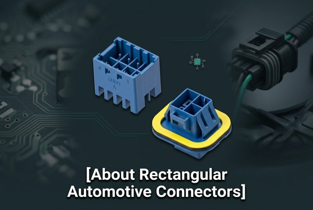
A rectangular automotive connector is an electrical interconnect whose mating interface is generally rectangular and whose components are selected for a defined vehicle or transportation application. Depending on the family, the assembly may include plug and receptacle housings, male and female terminals, wire seals or a mat seal, cavity plugs, a primary latch, and secondary assurance devices.
Its rectangular design can support multiple wires in a low-profile package within a complicated wiring layout. The connector creates a serviceable interface between electrical components, allowing power, signal, or data circuits to pass through the harness. Reliability, however, belongs to the complete connection system—not to the plastic housing alone. Terminal material and plating, conductor size and strand construction, crimp geometry, seal range, cavity assignment, mating alignment, and harness support all affect the result.
Common applications include engine and body control modules, lighting, infotainment, sensors, advanced driver-assistance systems, power distribution, and battery-management subsystems. Each location imposes different temperature, contamination, vibration, service-access, and electrical requirements.
Rectangular vs. Circular Automotive Connectors
Automotive connectors are available in many geometries; rectangular and circular are two common packaging families, not the only two connector types. Rectangular connectors often suit dense multi-circuit harness interfaces and ECU headers. Circular connectors can be attractive where rotational geometry, coupling hardware, or a particular sealed interface is advantageous. The correct choice depends on the qualified connector system and installation, not shape alone.
| Decision factor |
Rectangular format |
Circular format |
What to verify |
| Packaging |
Often supports low-profile, high-density circuit layouts and organized rows |
May fit round penetrations and radial layouts |
Envelope, rear wire-bend space, tool access, and keep-out zones |
| Circuit mix |
Can combine multiple power and signal circuits in one housing when the family permits |
Can also carry mixed circuits, depending on insert and contact options |
Cavity map, shielding or separation needs, and unused-cavity sealing |
| Keying |
Housing polarization and coded keys can help prevent cross-mating |
Keyways and shell orientation can provide similar mistake-proofing |
Unique mating pairs, color/coding controls, and drawing-defined orientation |
| Retention |
Commonly uses an integral latch plus CPA and/or terminal secondary lock |
May use bayonet, threaded, push-pull, or latch coupling |
Mating confirmation, lock engagement, service method, and retention test |
| Environmental protection |
Sealed families are available; performance depends on the complete mated assembly |
Sealed families are also available and may use shell-level sealing |
Exact test condition, mated state, fluid exposure, pressure, temperature, and aging sequence |
| Cost and assembly |
Unit-cost tendency may be favorable for dense harness assembly, but tooling and error-proofing matter |
Coupling hardware can add parts or time, while supporting specific service needs |
Total installed cost, cycle time, repair method, and quality controls |
Benefits and Engineering Trade-Offs
Compact size: The dimensions and mass of rectangular automotive connectors can make them suitable for restricted spaces. Circuit density should not come at the expense of wire bend radius, latch access, heat dissipation, or service clearance.
Versatility: Multiple pin configurations can integrate different circuits into a vehicle electrical system. For hybrid and electric vehicle designs, voltage class, touch protection, shielding, creepage/clearance, and interlock requirements may narrow the acceptable families; a low-voltage connector should never be assumed suitable for a high-voltage function.
Durability: Automotive connection systems may be designed for vibration, temperature cycling, moisture, and contaminants, but durability is not an absolute property. It must be tied to a defined test sequence, mounting condition, harness mass, mating-cycle limit, and acceptance criteria such as contact resistance or retention.
Assembly support: Polarization, keying, terminal position assurance (TPA), connector position assurance (CPA), and other secondary locks can reduce assembly ambiguity. A TPA or terminal secondary lock helps confirm and retain terminals in their intended seated position; a CPA helps secure or confirm the mated connector lock. Terminology and operation vary by supplier, so the controlled drawing and assembly instructions take precedence.
Rectangular Automotive Connector Specification Checklist
A complete specification should identify the entire matched system. Purchasing only by a housing part number can create hidden quality costs through mismatched terminals, seals, tools, or drawings.
| Specification item |
Questions to answer |
Required evidence |
| Circuit count and map |
How many active, spare, power, ground, signal, and data cavities are required? Are separation or shielding rules needed? |
Released pinout, cavity identification, and spare-cavity treatment |
| Electrical load |
What are normal, peak, inrush, and fault currents? What voltage class and allowable voltage drop apply? |
Load profile and supplier data for the exact terminal, wire, cavity loading, and ambient condition |
| Current/temperature derating |
How does capacity change with ambient temperature, adjacent loaded circuits, wire size, contact resistance, and enclosure heat? |
Applicable derating curves or test data; design margin documented for the installed condition |
| Terminal-wire compatibility |
Does the terminal accept the conductor area, insulation diameter, strand construction, and plating combination? |
Controlled application specification, crimp-height/width limits, pull-force criteria, and approved tooling |
| Seal compatibility |
Does each wire seal match the insulation diameter and cavity? Are unused cavities plugged correctly? |
Seal range, cavity-plug part number, lubricant limits if any, and assembly instructions |
| Polarization and keying |
Can nearby connectors be cross-mated or installed in the wrong orientation? |
Key code, color/cavity controls, mating drawing, and line-side error-proofing plan |
| Locks and assurance |
Are the primary latch, TPA/secondary lock, and CPA present and inspectable? |
Lock sequence, positive-stop or inspection feature, insertion/retention criteria, and service instructions |
| Environment |
Will the connector see splash, immersion, washdown, dust, oil, fuel, coolant, road salt, heat, or pressure change? |
Location-specific test plan; defined mated/unmated state and preconditioning |
| Mechanical duty |
What vibration spectrum, harness loading, shock, mounting stiffness, and mating-cycle count apply? |
Test method, fixture details, number of cycles, post-test electrical limits, and visual criteria |
| Change control |
Which dimensions, materials, plating, seals, and approved sources are controlled? |
Revision-controlled drawing, bill of materials, qualification report, deviations, and PCN/change process |
For sealing choices, an IP65 vs. IP67 comparison can clarify the code structure. The key boundary is that IEC 60529 classifies enclosure protection under specified dust and water tests. It does not by itself cover every automotive fluid, thermal shock, pressure-wash angle, capillary path, vibration sequence, or long-term installed condition. Validate the complete mated connection in its intended vehicle location.
A Practical Selection and Verification Workflow
- Freeze the application envelope. Document circuit functions, normal and abnormal loads, voltage class, ambient and self-heating limits, vehicle location, fluids, vibration, service access, mating frequency, and regulatory or customer-specific requirements.
- Build the cavity and compatibility matrix. Assign each circuit, then match the housing, terminal, wire, seal, cavity plug, CPA/TPA, backshell or clip, and tooling. Confirm part suffixes and key codes against controlled drawings. If an installed connector must be recognized, this guide to identifying automotive electrical connectors explains which physical details to record.
- Check electrical and thermal margin. Apply the supplier’s derating information to the actual number and location of loaded circuits, wire size, duty cycle, and maximum ambient. Prototype temperature-rise and voltage-drop checks should use production-representative crimps, routing, and enclosure conditions.
- Define assembly quality controls. Specify strip length, crimp settings, conductor and insulation crimp acceptance, terminal insertion, seal position, secondary-lock engagement, connector mating, and harness strain relief. Use approved applicators and inspection criteria rather than relying on a visual check alone.
- Review qualification evidence and validate the application. Ask for the report number, specimen configuration, test method/version, sample count, sequence, results, deviations, and exact part numbers covered. Then test gaps created by the actual mounting, harness mass, fluid set, temperature, electrical loading, and service profile.
Relevant standards help structure this work. USCAR-2 Revision 9 addresses performance testing of automotive electrical terminals, connectors, and components across development, production, and field analysis. ISO 8092-2:2023 provides terminology and test methods for general performance requirements of voltage-class-A wiring-harness connectors. SAE J2030:2025 concerns heavy-duty electrical connector performance, and IEC 60529 defines IP-code enclosure protection.
These documents are specifications or test methods; citing one is not a product certification. Applicability depends on the vehicle class, customer specification, destination market, connector location, and contract. A supplier should show evidence for the exact product configuration and revision rather than a logo or general statement.
Failure Modes and Verification Boundaries
- Terminal push-out or incomplete seating: verify insertion force, primary-lock engagement, secondary-lock closure, terminal retention, and cavity inspection.
- High resistance and local heating: verify conductor and insulation crimps, terminal plating, mating force, contact resistance, voltage drop, temperature rise, and current derating under representative loading.
- Water or contaminant entry: verify wire/seal diameter match, plug unused cavities, seal damage controls, mated-interface compression, and application-specific preconditioning. An IP code alone does not close these gaps.
- Fretting or intermittent circuits under vibration: verify mounting, harness support, wire exit direction, fixture stiffness, vibration spectrum, monitoring method, and post-test electrical criteria.
- Wrong-part or cross-mating errors: verify keying, polarization, color and label controls, connector-family differentiation, and line-side poka-yoke.
- Damage through repeated service: verify the specified mating-cycle limit, approved extraction tools, seal and latch inspection, and replacement criteria. Do not assume unlimited mating cycles.
Uses of Rectangular Automotive Connectors
Examples of automobile systems that may use rectangular automotive connectors include:
- Power distribution networks
- Entertainment and infotainment systems
- Navigation systems
- Engine and body control units
- Adaptive headlight systems
- Electric-vehicle and hybrid battery-management systems, where the selected family is qualified for the applicable voltage class
- Safety-related systems such as airbags and collision-detection systems, subject to the OEM’s functional-safety and validation requirements
Knowing the application is only the start. Automotive technicians, OEMs, harness manufacturers, and suppliers need the same released part numbers, revisions, drawings, crimp specifications, and validation boundaries. Buyers can use this overview of OEM automotive electrical connector sourcing to align technical and commercial checks.
Frequently Asked Questions
How many circuits should a rectangular automotive connector have?
Choose enough cavities for the released circuit map, required grounds and shields, and any deliberately approved spares. More cavities are not automatically better: added size, cost, heat concentration, and unused-cavity sealing must be considered.
Can I use the catalog current rating for every terminal?
No. Treat a catalog rating as conditional on the stated terminal, wire, ambient temperature, test setup, and number of loaded circuits. Use the applicable derating data and verify temperature rise and voltage drop in a production-representative assembly.
Does an IP67 connector automatically pass automotive sealing requirements?
No. IP67 describes protection under a defined IEC 60529 water-ingress test; it does not automatically represent every vehicle fluid, thermal cycle, pressure wash, vibration sequence, or harness leak path. Confirm the rated state and validate the installed connection against the location-specific requirement.
What is the difference between CPA and TPA?
CPA generally refers to connector position assurance for the mated housing lock, while TPA generally refers to terminal position assurance or a terminal secondary lock. Supplier terminology differs, so confirm the device function, engagement sequence, and inspection method on the controlled drawing.
What documents should a connector supplier provide?
Request controlled component and mating drawings, application/crimp specifications, approved wire and seal ranges, tooling data, derating information, material and plating details, change-control terms, and qualification reports. Each report should identify exact part numbers, test version, specimen configuration, results, deviations, and scope.
References and Further Reading
The practical rule is simple: qualify the connection system and its installed condition, not just the housing name or headline rating.
ZUCH can help buyers review connector configuration, compatibility documentation, and sourcing requirements without substituting for the OEM’s application validation. Explore ZUCH connector options and contact the team with your circuit map, wire sizes, environmental conditions, drawings, and required evidence.
 Zhejiang ZUCH Technology Co., Ltd.