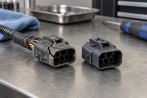
Zhejiang ZUCH Technology Co., Ltd.
When a harness engineer receives a terminal sample that appears to fit the specified wire gauge, the quickest decision can become the costliest one. The conductor may crimp, yet the terminal may not seat in the housing, the insulation support may miss the cable diameter, or the locking feature may fail to engage. Those errors can surface as assembly rework, intermittent circuits, or field-service replacement rather than an obvious incoming defect. The central problem is not simply finding a conductive metal contact; it is confirming a complete matched system. This guide explains how procurement and engineering teams can screen terminal-family compatibility, conductor and insulation range, plating, electrical duty, approved crimp tooling, and housing retention before releasing a part.
Check These Four Items Before Approving a Terminal
The short answer is: begin with the connector family and exact cavity, then validate conductor cross-section and strand construction, insulation outside diameter and seal range, contact geometry and plating, electrical duty, tooling, and retention. Wire gauge is only one input when choosing automotive connector terminals. SAE/USCAR-21-4 provides performance requirements and test methods for solderless cable-to-terminal crimps, but it does not certify a terminal as compatible with every housing. Use the terminal manufacturer’s application specification and drawing, then compare those records with the vehicle’s wiring and service documentation. Release the selection only when the terminal, wire, seal, applicator, housing lock, and mating contact form one documented system.
Confirm the Connector Family Before Selecting Wire Gauge
A terminal is designed around a particular contact interface and retention system. Its mating geometry, contact orientation, locking lance or retention shoulder, cavity keying, insertion direction, and secondary-lock interaction must agree with the specified housing. A terminal that accepts the same nominal wire size can still be the wrong contact for that cavity.
Match the exact terminal and housing records
Start with the housing part number and revision, then identify the terminal part numbers that the housing manufacturer lists for that cavity. Confirm contact gender, mating interface, cavity position, primary retention feature, and any terminal-position-assurance or secondary-lock requirement. The TE Connectivity terminals and connectors catalog illustrates why terminals, housings, accessories, and tooling are treated as related system elements rather than generic pieces.
A visual fit is not release evidence. If a sample slides into a cavity but its retention feature does not engage at the intended location, assembly handling or connector mating can move the contact. Likewise, a contact that resembles the intended terminal can have a different mating beam or tab geometry. Procurement should therefore request a controlled drawing or manufacturer cross-reference rather than accept a similarity-based substitution.
Check the conductor and insulation as separate dimensions
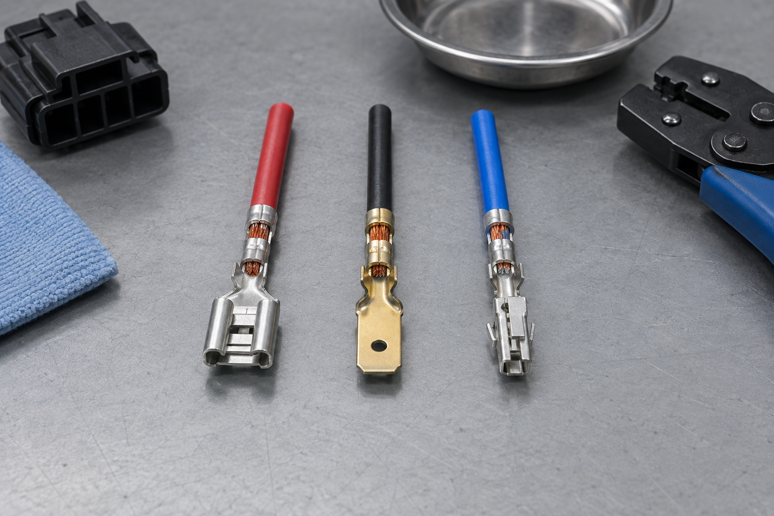
Nominal wire gauge does not fully define a cable. Two wires with the same nominal conductor area may differ in strand count, strand diameter, conductor construction, insulation material, and insulation outside diameter. The conductor wings must form the specified crimp around the actual conductor, while the insulation support must grip or support the cable without cutting it or remaining too loose.
For sealed connectors, the insulation outside diameter also affects seal selection and sealing compression. The correct workflow is to compare the cable specification with the terminal’s conductor range, insulation range, and the seal manufacturer’s approved range. This is why the phrase automotive terminal connectors should be treated as a system-selection problem, not a gauge-only catalog search.
Match Plating to Current, Temperature, and Operating Conditions
Plating cannot be selected by a universal “tin is standard, gold is better” rule. The correct surface depends on the approved mating pair, signal or power function, environment, expected cycling, and the manufacturer’s validated connection system. Tin- and gold-plated contacts should be compared only within documented application boundaries; plating color or reputation is not proof of suitability.
Treat plating as part of the contact system
First confirm the plating specified on both sides of the mating interface. Then review the terminal supplier’s application data for the intended environment and electrical use. If a proposed change alters the contact material, finish, thickness designation, or mating surface, route it through engineering change control and system validation instead of classifying it as a purchasing equivalent.
The practical purchasing question is not which plating is universally superior. It is whether the exact terminal pair has manufacturer documentation and vehicle-level approval for the circuit, exposure, and service conditions. Where the available documents do not support the proposed pairing, the correct decision is to stop the substitution rather than infer compatibility.
Evaluate electrical duty as a combined condition
A catalog current value, when supplied, is not a stand-alone system rating. Conductor size and material, contact resistance, ambient temperature, temperature rise, cavity loading, enclosure conditions, duty cycle, vibration, mating condition, and derating rules can all affect the application decision. Continuous load, intermittent load, and low-level signal service therefore require different validation questions even when the contacts look identical.
Engineering should define the actual load profile and worst-case operating environment before asking a supplier to confirm suitability. The Molex automotive connection systems overview shows the breadth of system families and application contexts, but a family overview does not replace the part-level specification, test report, or vehicle validation required for release.
What Do Crimp Tooling and Retention Add to the Decision?
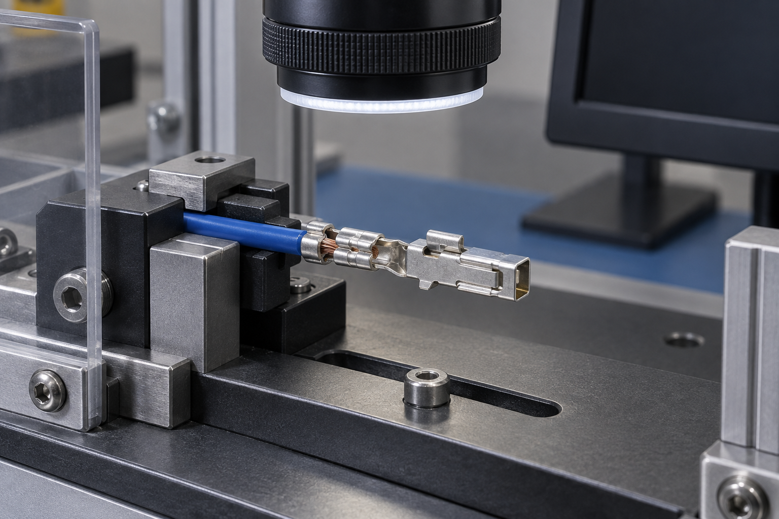
The terminal choice is incomplete until the production crimp process is defined. SAE/USCAR-21-4 covers performance requirements and test methods for solderless cable-to-terminal electrical crimps; it is a crimp-performance specification, not a declaration that terminals from different families are interchangeable. The supplier’s application specification still controls details such as the approved applicator, wire preparation, target crimp geometry, inspection method, and permitted process window.
Tooling must be tied to the terminal and wire combination
Hand tools, service tools, and production applicators may serve different purposes and may not create the same controlled result. Before production release, record the exact terminal, wire, applicator, press setup, inspection criteria, and maintenance plan. A sample that merely survives a hand pull is not a substitute for the specified crimp validation sequence.
The commercial effect is direct: an inexpensive terminal substitution can create tooling changes, setup scrap, inspection burden, line stoppage, and service risk. Those costs belong in the total-cost decision. A documented crimp process reduces ambiguity for incoming inspection, production quality, and later fault analysis.
Retention requires more than a successful insertion
After crimping, confirm terminal orientation, insertion depth, primary-lock engagement, secondary-lock position, and the applicable retention check. The female contact also has to preserve its intended mating geometry; probing, mishandling, or a mismatched tab can compromise contact behavior even if the terminal remains inside the housing.
Which Terminal Choices Affect Cost and Service Life?
The following comparison helps purchasing teams assess automotive electrical connector terminals beyond piece price. The “hidden cost” column does not predict a failure; it identifies the cost category that becomes relevant when a required verification is omitted.
| Selection variable | Evidence for a controlled choice | Risk when treated as generic | Consideración del TCO |
|---|---|---|---|
| Terminal family and contact geometry | Manufacturer drawing, housing compatibility record, and mating-interface definition | Incomplete seating, incorrect mating, or lock misalignment | Rework, sorting, replacement, and engineering review |
| Conductor construction and range | Cable specification plus terminal application specification | Crimp outside the approved process envelope | Setup scrap, extra inspection, and process instability |
| Insulation OD and seal range | Measured cable OD, insulation-support range, and seal specification | Poor strain support or an unverified sealed interface | Containment, repair, and validation work |
| Plating and mating pair | Part-level finish specification and approved mating-system data | Unsupported material or interface substitution | Change control, retesting, and supply disruption |
| Current, temperature, and duty cycle | Defined load profile, environmental conditions, and system validation | Using a catalog value outside its stated conditions | Derating review, redesign, or field-service exposure |
| Applicator and crimp control | Approved tooling, setup criteria, inspection plan, and crimp test records | Variable conductor or insulation crimp formation | Tooling, maintenance, scrap, and quality labor |
| Primary and secondary retention | Insertion instruction, lock-position criteria, and retention verification | Terminal movement or incomplete assembly | End-of-line diagnosis and connector replacement |
A Practical Order for Selecting an Automotive Terminal
A gated sequence prevents a low-cost part from advancing before its system evidence exists. Each gate should be closed with controlled documents, samples, and validation appropriate to the program; passing one gate does not waive the next.
| Decision gate | Questions to answer | Preferred evidence | Release condition |
|---|---|---|---|
| 1. Family and cavity | Is this exact contact approved for the housing cavity and mating half? | Controlled drawings and manufacturer compatibility data | Part numbers, revisions, and interface agree |
| 2. Wire and seal envelope | Do conductor construction, cross-section, insulation OD, and seal range align? | Cable, terminal, and seal specifications | The actual production cable falls within every documented range |
| 3. Surface and electrical duty | Are mating finish, load profile, temperature, environment, and duty supported? | Part-level application data and program requirements | No condition relies on an assumed catalog equivalence |
| 4. Crimp process | Is the approved applicator available, controlled, and validated for this wire? | Application specification, setup record, and test plan | Production samples meet the defined acceptance criteria |
| 5. Housing retention | Are primary retention, secondary lock, and terminal position verifiable? | Assembly instruction and retention inspection criteria | The assembled connector passes the specified checks |
| 6. Vehicle documentation | Does the released circuit documentation permit this exact configuration? | Vehicle drawing, harness specification, and service information | The configuration is approved for the intended circuit and market |
Which Documents Govern Performance, Application, and Vehicle Use?
Three document layers answer different questions. Combining them into one vague claim creates avoidable compliance and sourcing risk.
Use Performance Specifications to Evaluate the Crimp
SAE/USCAR-21-4, Performance Specification for Cable-to-Terminal Electrical Crimps, addresses requirements and test methods for solderless cable-to-terminal crimps. The USCAR Electrical Wiring Component Application Partnership provides the program context for electrical wiring component specifications. Conformance to a crimp specification does not, by itself, approve a terminal for an unrelated housing, mating interface, or vehicle circuit.
Use Manufacturer Specifications to Confirm the Terminal System
The terminal or connector manufacturer defines the applicable part numbers, cable envelope, mating parts, tools, assembly instructions, and inspection requirements. These records govern the production use of specific automotive wire terminals and connectors. A supplier catalog helps identify candidates, but the controlled drawing and application specification should govern release.
Use Vehicle Documents to Confirm the Installed Circuit
Vehicle and harness documentation assigns the circuit, cavity, wire, seal, routing, repair method, and any program-specific validation. It can be more restrictive than a general component specification. Unsupported substitutions can trigger requalification, production containment, warranty exposure, or rejection by the customer even when the individual crimp appears acceptable.
Final Checks Before Releasing a Terminal for Production
- Lock the system identity. Record the housing, terminal, mating contact, seal, secondary lock, and drawing revisions before requesting quotes.
- Send the actual cable specification. Include conductor construction and insulation OD, not only an AWG or square-millimetre label.
- Require process evidence. Ask which applicator and inspection criteria apply, then align the production plan with a documented automotive connector crimping process.
- Verify retention separately. Review positive-locking and secondary-retention principles as well as the checks used for female terminal contact retention.
- Evaluate exceptions as engineering changes. A thin-wire or alternate-orientation requirement may need a purpose-designed approach; this 250 flag terminal thin-wire example shows why geometry, wire, and process have to be reviewed together.
Once these inputs are controlled, ZUCH can support sourcing discussions by comparing documented terminal, housing, wire, and tooling requirements across applicable product families. That supplier review should complement—not replace—the manufacturer’s application specification and the customer’s vehicle-level approval process.
Frequently Asked Questions
How do I match an automotive terminal to a connector housing?
Use the housing part number and revision to find the manufacturer’s listed terminal for the exact cavity and mating interface. Confirm contact gender, keying, orientation, primary retention, and secondary-lock interaction; do not approve a terminal only because it slides into the cavity.
Is wire gauge alone enough to choose an automotive connector terminal?
No. Verify conductor cross-section and strand construction, insulation OD, terminal family, seal range, plating, contact geometry, electrical duty, approved applicator, and housing retention. The actual production cable must fall within every applicable documented range.
Why does wire insulation diameter matter when selecting terminals and seals?
Insulation OD determines how the insulation support engages the cable and whether the selected seal operates within its specified range. A conductor can be acceptable while the insulation or seal interface is not, so both dimensions require separate checks.
When should I choose tin-plated versus gold-plated automotive terminals?
Choose the finish specified for the approved mating pair and application, considering electrical function, environment, cycling, and manufacturer data. Neither finish is universally superior, and an unvalidated finish change should be handled through engineering change control.
How do current, temperature, and duty cycle affect terminal selection?
They define the electrical and thermal conditions the complete connection must support. Review the actual load profile, ambient conditions, cavity loading, conductor, mating contact, and applicable derating or validation data rather than treating one catalog current value as universal.
Can terminals from different connector families be used interchangeably?
Not unless the relevant manufacturers and vehicle documentation explicitly approve the substitution. Similar wire ranges or compliance with a crimp test specification do not establish equivalent contact geometry, housing retention, plating, sealing, or mating performance.
References
- SAE International, USCAR21-4: Performance Specification for Cable-to-Terminal Electrical Crimps.
- TE Connectivity, Terminals and Connectors catalog.
- USCAR Electrical Wiring Component Application Partnership, EWCAP Specifications and Program Information.
- Molex, Automotive Connection Systems.
Conclusion: Approve the System, Not an Isolated Terminal
The governing decision rule is simple: a terminal is acceptable only when its connector family, wire envelope, mating finish, electrical duty, crimp process, and retention method are documented as one compatible system. Start with the housing and cavity, confirm the actual conductor and insulation dimensions, evaluate plating and duty conditions, then validate the approved tooling and assembled retention. Never skip part-level application data or vehicle-specific authorization merely because a sample fits or a crimp meets one performance specification. That shortcut cannot establish interchangeability. When buyers need to compare candidate parts after these requirements are defined, ZUCH can help organize the sourcing review across its connector and terminal product directory. Share the controlled housing, wire, mating, environmental, and tooling requirements to begin a documented technical discussion.