Zhejiang ZUCH Technology Co., Ltd.
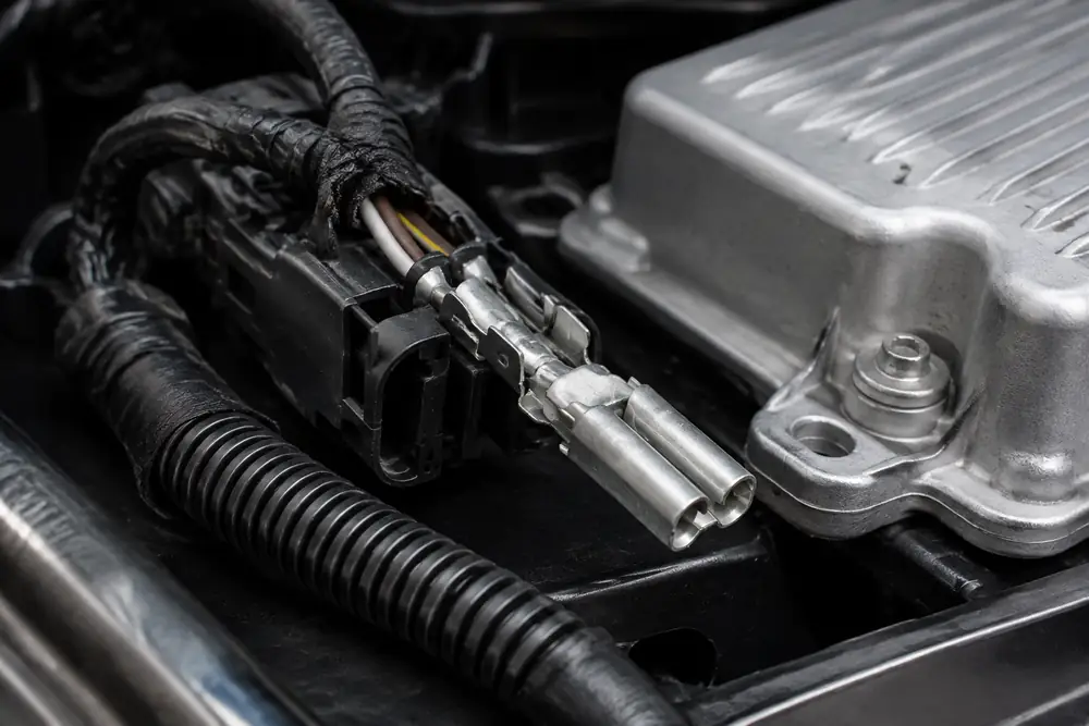
When an automotive validation engineer in Detroit saw a low-voltage actuator fault appear after thermal cycling, a small voltage drop turned an otherwise steady signal into an intermittent one. The initial suspicion was a bad part; the investigation instead traced the fault to interface resistance shaped by terminal material, plating choice, mating condition, and incomplete maintenance control.
Resumen: Contact resistance is the electrical opposition at a mated terminal interface, and it can convert into voltage loss and heat according to V = I × R and P = I² × R. A four-wire, or Kelvin, low-resistance measurement separates lead resistance from the connection under test; it is therefore more useful than a basic two-wire reading for comparing low-ohm interfaces. Specify the terminal finish, force, sealing, validation plan, and service inspection around the actual circuit current and environment—not around a visual pass alone.
In vehicle harness work, the concern is whether a changing interface disrupts a load, sensor, actuator, or diagnostic threshold. The same logic applies to equipment built with automotive electrical connectors oem supply requirements: an assembled connection can still lose electrical margin as vibration, temperature, contamination, and fretting act on the contact zone.
How interface resistance becomes a voltage-drop and heat problem
A mated connector does not conduct through its entire apparent contact area. Current passes through microscopic asperities where normal force and surface condition create conductive paths. Oxide films, debris, low contact force, poor crimp transfer, or relative motion can reduce those paths, which matters when current rises or circuit margin is narrow.
The governing calculation is straightforward. In an illustrative 10 A circuit, an added 10 mΩ of interface resistance creates 0.10 V of drop and 1 W of localized heating. At 20 A, the same resistance creates 2 W because heat follows the square of current. That concentrated heat can accelerate relaxation, discoloration, polymer aging, or further film growth; this feedback loop explains why a modest measurement change can become a field failure rather than merely a laboratory observation.
For signal circuits, the issue may be less thermal and more diagnostic. A changing ground or supply reference can alter what an electronic control unit sees, especially during crank or load switching. Compare stable bulk-conductor resistance with mated-interface readings before and after the relevant vibration, thermal, humidity, or mating exposure. This is why automotive terminal connectors must be considered as electrical interfaces, not just retention features.
A total-cost view also matters: a low-cost terminal that drives debugging, service returns, or oversized circuit margin may cost more than a controlled contact-system choice. Quantify the circuit margin and validation exposure before release.
Measure contact resistance with the right low-resistance method
For a connector interface, a two-wire meter reading includes the resistance of test leads, probes, fixtures, and contact points. That is often too much uncertainty when the device under test is in the milliohm range. A four-wire Kelvin method drives a known test current through one pair of leads and senses voltage with a separate high-impedance pair directly across the connection. Dividing sensed voltage by current produces the resistance while minimizing lead-drop influence.
Use controlled probe placement, a fixture that does not disturb the terminal, documented test current, calibrated equipment, and a repeatable sample condition. Record whether the value is initial or follows mating, vibration, or environmental exposure. A single low reading without that context is not evidence of service durability.
| Diagnostic question | Recommended observation | What the result can indicate | Next action |
|---|---|---|---|
| Is a loaded circuit losing voltage? | Measure supply-to-load and return-path drop under the relevant load state. | A localized drop can separate harness or connection loss from a load fault. | Measure across individual interfaces before replacing components. |
| Is the connector interface changing? | Use a four-wire Kelvin resistance reading across the mated terminals. | Variation across comparable samples or exposures can suggest interface instability. | Document fixture, current, sample state, and repeat readings. |
| Is heat concentrated at the joint? | Compare temperature rise and nearby conductor temperature during controlled loading. | Local heating can align with I²R loss, but needs correlation with current and ambient conditions. | Inspect terminal force, crimp, plating, and mating condition. |
| Is service handling involved? | Inspect for incomplete seating, damaged seals, moisture paths, or unintended terminal spread. | A connection may pass bench continuity yet fail after movement or environmental exposure. | Correct assembly controls and define a service inspection step. |
Voltage-drop testing and Kelvin resistance testing answer related but different questions. The first shows the installed circuit consequence during operation; the second characterizes the connection interface more directly. Together they help teams avoid treating continuity as a complete functional test. For harness process context, see how to crimp automotive terminals.
Match plating, base material, and environment to the duty cycle
Base alloy, spring geometry, plating system, lubricant strategy, and housing sealing work as a system. Copper alloys support conductivity, while the terminal design must retain sufficient normal force across temperature and vibration. Tin-based finishes are widely used in appropriate applications; noble-metal finishes can be selected where low-level signal integrity, corrosion exposure, or mating behavior justify them. The right choice depends on the mating pair, current, temperature, atmosphere, insertion frequency, and approved process. For a related technical reference, see Materiales de conectores: Aleación de cobre frente a contactos de latón.
Plating is not decorative. Its thickness, porosity, mating compatibility, and fretting behavior determine whether the interface stays controlled. Sourcing teams should request material declarations, plating callouts, mating-terminal definitions, and change-control information rather than compare parts by outline alone.

| Design factor | Effect on contact resistance | Trade-off to evaluate | Verification focus |
|---|---|---|---|
| Contact normal force | More stable conductive asperities generally reduce sensitivity to film disruption. | Force must still allow intended insertion, retention, and long-term relaxation behavior. | Mating force, retention, vibration, and thermal aging tests. |
| Terminal alloy and geometry | Influences conductivity, spring retention, and stress relaxation. | Electrical performance must be balanced with forming and mechanical durability. | Material control and temperature-exposure evaluation. |
| Plating system | Shapes corrosion behavior, fretting response, and initial interface stability. | Cost and finish selection must fit the mating pair and operating environment. | Environmental exposure and mating-cycle comparison. |
| Sealing and connector position | Limits moisture and contaminant access to the interface. | Sealed designs need compatible wire seals and disciplined assembly. | Ingress, temperature, and service-condition checks. |
| Crimp and wire preparation | Can add resistance outside the mating interface or create heat near it. | Process capability matters as much as nominal terminal design. | Crimp monitoring and voltage-drop investigation under load. |
In procurement language, automotive connectors electrical performance depends on more than pin count and current class. Specify the contact family, terminal orientation, cable size range, expected mating cycles, exposure profile, and acceptable evidence package. This prevents a connector automotive purchase from becoming a late-stage compatibility experiment.
Use standards, selection controls, and maintenance to preserve performance
Standards guide validation questions, but a standard reference is not automatically a product certification. SAE/USCAR-2 addresses automotive connector performance requirements and test methods; IEC 61984 addresses safety requirements and tests for connectors. Applicability depends on the destination market, equipment function, customer specification, and sales claims. Unsupported compliance language can create qualification risk.
For automotive electrical connector pins, preventive maintenance begins with preserving the validated interface. Do not burnish, bend, lubricate, or substitute terminals in the field unless the connector system documentation specifically permits it. Service teams should check latch engagement, terminal position assurance, seal condition, wire strain relief, heat evidence, and mating contamination; then use controlled voltage-drop or Kelvin checks when symptoms point to an electrical path.
A practical sourcing and release checklist is:
- Map each circuit’s continuous and transient current, voltage margin, and allowable temperature exposure.
- Specify the approved mating terminal, plating family, wire range, and crimp process as one controlled system.
- Choose environmental and mechanical test sequences that reflect vibration, thermal cycling, humidity, fluid exposure, and service access where relevant.
- Require traceable drawings, material and plating information, test evidence, and engineering-change notification from the supplier.
- Plan diagnostics around loaded voltage drop and four-wire contact-resistance trending, rather than continuity alone.
For buyers evaluating automotive electronic connectors, ZUCH can provide product-selection information, drawings, and documentation to align a connector family with the application. See this guide to automotive electrical connectors and the importance of automotive connector standards.
What is contact resistance in an automotive connector?
It is the electrical resistance at the joined surfaces of mated terminals, separate from the resistance of the wire and bulk terminal material. It is influenced by contact force, surface finish, cleanliness, geometry, and environmental history. A low value matters because it helps preserve voltage margin and limit I²R heating under load.
Why does contact resistance increase over time?
Thermal cycling, vibration, fretting, corrosion, contamination, loss of contact force, and poor service handling can change the interface. A resistance increase can also originate from a crimp or conductor issue near the connector, so diagnosis should isolate the path rather than assume the mated contact is solely responsible.
Can high contact resistance cause a vehicle fault?
Yes. It can create enough voltage drop or localized heat to affect an actuator, sensor reference, module supply, or charging path. The symptom may be intermittent because load, temperature, and movement change the condition; test the circuit under the state in which the fault occurs.
How do you measure connector contact resistance?
Use a four-wire Kelvin method when characterizing a low-resistance mated interface: one pair supplies known current and a separate pair senses voltage at the test points. Record the test current, fixture, probe locations, temperature, and sample condition; compare results through the intended environmental or mechanical sequence.
Does terminal plating affect contact resistance?
Yes. Plating affects film formation, corrosion response, fretting behavior, and compatibility with the mating terminal. It should be chosen as part of a validated contact system, not changed independently for appearance or nominal cost.
When should a high-resistance automotive connector be replaced?
Replace or repair it according to the vehicle manufacturer’s service procedure and the confirmed failure mode. If readings, heat evidence, damaged terminals, or failed retention indicate an unstable interface, identify whether the cause is the terminal, housing, seal, crimp, wire, or assembly process before installing a replacement.
References and the next sourcing step
Useful primary references for defining a test and documentation plan include:
- SAE/USCAR-2, Performance Specification for Automotive Electrical Connector Systems
- IEC 61984, Connectors—Safety requirements and tests
- NIST Physical Measurement Laboratory
The durable decision is rarely “does it conduct today?” but “will the controlled interface retain margin throughout its real duty cycle?” When your team is ready to align application requirements with a connector family, review ZUCH products and contact ZUCH with the circuit, environment, and documentation requirements for a focused discussion.