Zhejiang ZUCH Technology Co., Ltd.
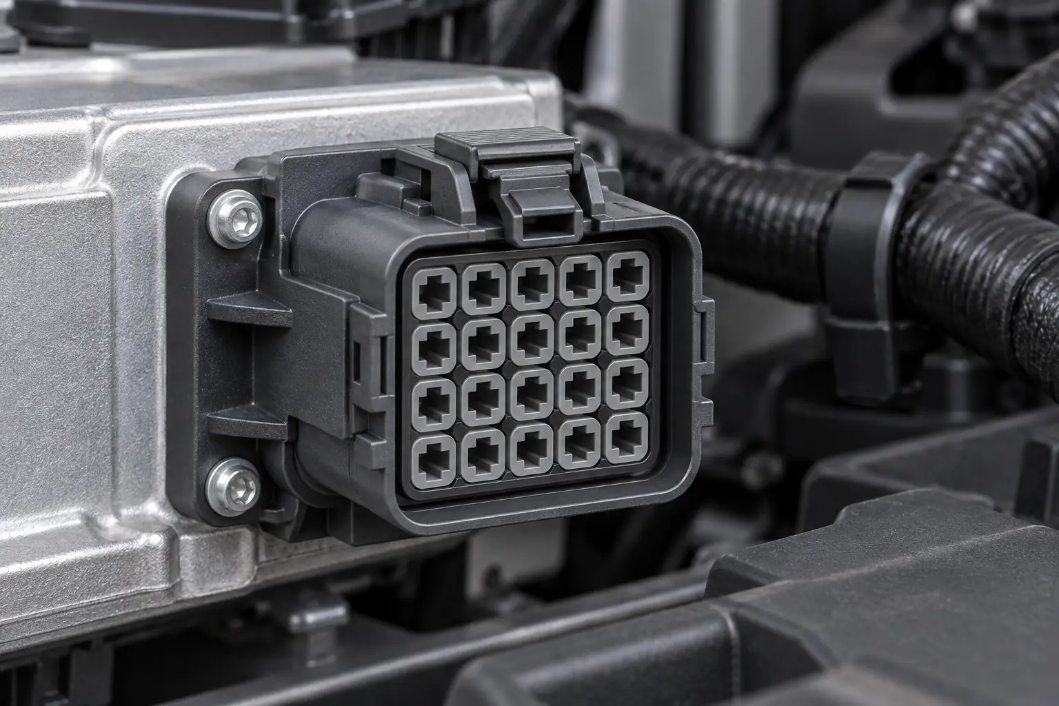
When an integration engineer in Detroit encountered repeated module faults during a prototype build, he traced every labelled wire and found continuity—but several inputs still changed state as soon as the ignition was enabled. He had mapped the 20 circuits from the connector’s wire-entry face while the module drawing showed the mating face, so the two-row layout had been mirrored. The connector was not defective; the interface definition was.
Resumen: Match a 20 pin automotive connector as a controlled interface, not as a cavity count. Declare the viewing face, map all 20 cavity numbers to circuit functions, and verify the exact mating housing, key, terminal family, wire range, seals and lock features before crimping. SAE/USCAR-2 and ISO 8092 provide automotive connector performance and test frameworks, but neither makes two look-alike parts interchangeable. Release the design only after position-by-position continuity, retention and application-specific electrical checks.
Why Must the Module-to-Harness Interface Be Defined Before Housing Selection?
A 20-position interface can combine sensor signals, controls, communication pairs, power and grounds at a module or sub-harness; the cavities are not necessarily electrically identical. Before selecting parts, record each cavity’s function, source and destination, voltage, current, wire size, insulation diameter and any shielding or twist requirement. Cross-reference the module, harness and supplier drawings by revision.
Orientation is part of that definition. State mating face or wire-entry face, latch position and cavity 1; opposite-face views can mirror two rows. Use a keyed outline plus two landmarks, then confirm three non-adjacent cavities before populating the remaining 17.
A Correct 20-Way Connection Requires a Documented Mating Pair and Key Code
The mating plug must share the approved family and key code. Compare part numbers, drawings, latch, polarization, terminal system, pitch and secondary locks. Starting to engage does not prove compatibility; partial engagement can spread contacts, leave a seal uncompressed or produce an intermittent latch.
State housing style and metal-contact sex separately—for example, “plug housing with receptacle contacts”—because male/female terminology varies. An inline connection needs a matched housing pair; a harness plug connected to a module instead uses the module header as its defined mate. Keying prevents a wrong mate, not a wrong circuit map, so never alter ribs or approve a substitute by outside dimensions alone.
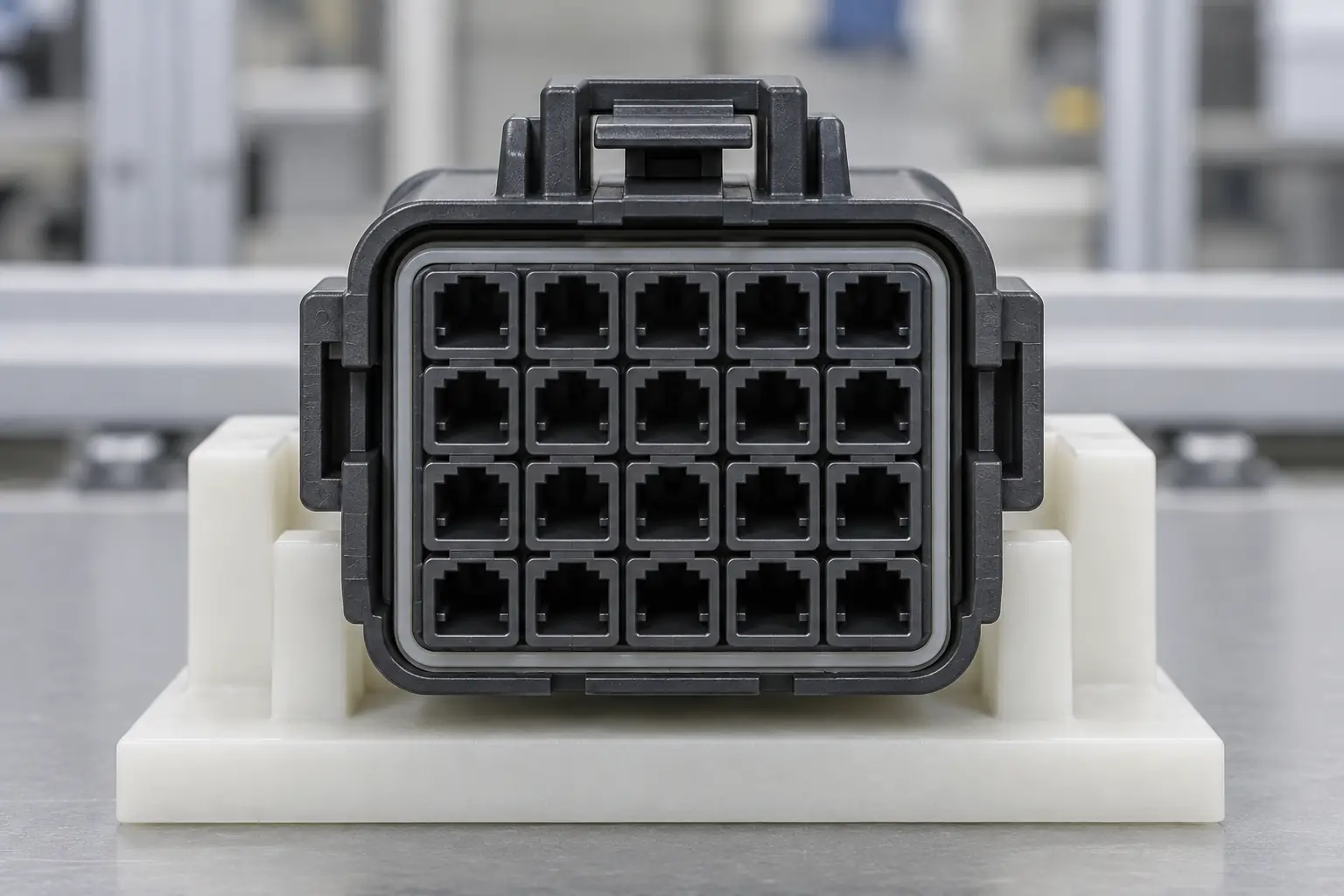
Each Cavity Needs a Terminal Matched to Its Wire and Electrical Duty
Terminal selection is position-specific. Catalogues may offer variants spanning roughly 0.35–2.5 mm² (about 22–14 AWG), but that is not a universal rating for a 20 pin automotive connector. The selected terminal specification must cover the conductor, strand construction and insulation diameter; mixed loads may require more than one contact size.
Current capability also depends on contact design, plating, crimp quality, temperature, duty cycle and adjacent loaded circuits. Illustratively, a 10 mΩ connection dissipates 0.4 W at 6 A but 1.6 W at 12 A because loss follows I²R. Gauge alone cannot establish a current rating.
For open-barrel contacts, approve the terminal, seal, wire, strip length, tooling, crimp-height window, pull-force criterion and inspection method as one process. On sealed systems, match the wire seal to insulation diameter and plug unused cavities; a loose or torn seal defeats the design.
How Can You Validate a 20-Position Pinout Before Production or Repair?
First, treat “20-pin” as a housing description, not proof of 20 active circuits. A 20-position shell may contain fewer populated terminals; unused locations can be open, fitted with cavity plugs for sealing, or physically blocked by the design. Record each state explicitly in the cavity table so an empty position is not mistaken for a missing contact or omitted test.
Use the cavity-number reference on the released drawing—not a photograph, wire sequence or assumed left-to-right order. Mark whether each drawing shows the connector face or the wire-entry face, then add the latch/key orientation and cavity 1. Compare the harness-side and mating-header drawings together because suppliers may present opposite viewing faces. Repeated wire colours require circuit labels or endpoint tracing; colour alone cannot distinguish two functions.
Build a 20-position continuity matrix from the released documents, including every populated, empty and blocked cavity. With power removed and electronics isolated as required, test each harness endpoint to its intended cavity. Keep power feeds and grounds clearly separated in the map, verify polarity for diodes, actuators and communication pairs, and test each circuit for isolation from adjacent cavities as well as unintended continuity to power or ground. A multimeter beep proves only that the meter’s internal threshold was crossed, not acceptable resistance under load.
A Five-Step Check Prevents Mirrored, Shifted and Partially Populated Pinouts
- Normalize both drawings. Label face, latch or key, cavity 1 and revision on the connector and mate documents.
- Classify all 20 positions. Mark each as populated, intentionally empty or blocked, and assign the documented circuit name.
- Map endpoint to cavity. Trace repeated-colour wires individually and record continuity rather than inferring identity from insulation colour.
- Check isolation and polarity. Test adjacent positions and power/ground separation; confirm pair orientation and polarity where the circuit requires them.
- Resolve every discrepancy. Do not release production or reconnect a repaired module until the physical build, both mating drawings and the signed test record agree.
Where allowed, record resistance or run an approved loaded voltage-drop test against vehicle and harness limits. Communication circuits may also need polarity, pair-integrity and network checks. Never use an insulation-resistance tester on connected electronics unless the OEM procedure expressly permits it.
For one damaged terminal, de-energize the circuit, release the secondary lock and use the specified extractor. Fit the approved contact and seal, inspect the cavity, verify retention, relock and retest. Replace a cracked, heat-damaged, distorted or non-retaining housing. This controlled repair is usually less costly than diagnosing an intermittent cross-circuit after installation.
Which Sourcing or Repair Path Best Controls Compatibility Risk?
| Approach | Compatibility evidence | Performance focus | Cost and maintenance implication |
|---|---|---|---|
| Documented housing-and-mate set | Supplier drawings, approved mate list and exact key code | Complete terminal, seal and lock system can be validated | Moderate component cost; traceability lowers integration and sourcing risk |
| Approved pigtail or adapter | Verified pin-to-pin map, wire data and splice specification | Adds splice points and packaging length | Above bare-housing repair; faster service, but extra joints need control |
| Single-terminal repair | Approved service contact, seal, tooling and intact cavity | Suitable only when retention and sealing surfaces remain sound | Low part cost; skilled extraction, crimping and retest required |
| Visually similar substitute | Appearance only | Unknown keying, contact force, sealing and latch engagement | Apparently low cost; high rework and return risk |
Record These Five Controls Before Ordering a 20-Position Interface
| Control dimension | Record before ordering | Verification method | Failure prevented |
|---|---|---|---|
| Orientation and pin numbering | Viewing face, latch, cavity 1 and revision | Overlay drawings; check three non-adjacent positions | Mirrored or rotated circuit map |
| Mating hardware | Housing/header numbers, key, latch and secondary locks | Drawing review plus full mate/unmate inspection | Partial engagement and wrong-mate damage |
| Terminal and wire | Contact, sex, conductor area, insulation OD and tooling | Crimp measurement, inspection and specified pull test | High resistance, strand damage and wire pull-out |
| Environment | Temperature, fluids, vibration, splash and mating cycles | Agreed SAE/USCAR-2 or ISO 8092-based sequence | Corrosion, fretting, seal leakage and latch fatigue |
| Electrical release | Functions, loads, voltage drop and network constraints | Continuity/short matrix, voltage drop and module test | Crossed circuits, open circuits and false module faults |
Applicable Standards Define Test Scope, Not Universal Interchangeability
- SAE/USCAR-2: This automotive connector-system performance specification defines electrical, mechanical and environmental tests. It is a qualification framework, not proof that a generic 20-way part suits a module or vehicle zone; state the revision, category, sample build and limits.
- ISO 8092-2: This road-vehicle standard addresses definitions, test methods and general performance requirements for on-board harness connections. Specify the applicable edition and OEM additions; it does not replace drawings or application validation.
- IEC 61984:2008: This gives safety requirements and tests for connectors above 50 V through 1,000 V AC/DC and up to 125 A per contact; it can guide work at or below 50 V. It is not vehicle-specific and does not replace automotive or OEM requirements.
These documents contain requirements or test methods, not blanket product certifications. Tie every claim to a part configuration, assembled wire set, edition, test report and destination-market programme; unsupported claims invite rejected samples and repeated testing.
How Should Buyers Specify and Source the Right 20-Way Connection?
- Freeze the interface. Release a controlled cavity table naming the viewing face and all 20 circuits.
- Identify both sides. Confirm housing or header part numbers, terminal sex, keying, latch, secondary locks and accessories. If the installed part is unknown, follow a structured guide to identifying automotive electrical connectors.
- Match wire and process data. State conductor and insulation dimensions, terminal and seal numbers, tooling and crimp criteria. Review the controls for crimping automotive connectors.
- Define the environment and validation. Specify circuit loads, temperature, vibration, fluids, splash or immersion exposure, mating cycles and the exact test sequence.
- Approve representative samples. Validate the intended wire, seals and tooling; retain drawings, results and traceability.
ZUCH can support interface discussions when buyers provide the mating drawing, cavity map, wire dimensions, loads, environment and evidence requirements. No model or performance level should be assumed from cavity count alone.
Frequently Asked Questions
What is a 20-pin automotive connector typically used for in module and harness interfaces?
It provides a compact, serviceable interface between a harness and an ECU, control module, junction device or sub-harness. Because the 20 positions may mix power, ground, signals and communications, each cavity needs documented electrical and wire requirements.
How do I confirm that a 20-pin automotive connector matches my vehicle wiring?
Confirm the family, key, mate, viewing orientation, cavity map, terminals, wire dimensions, seals and loads. Use released drawings rather than photographs; this overview of automotive wire connector types helps frame the comparison. Test every position for continuity and unintended shorts before connecting the module.
Do 20-pin automotive connectors need a matching male and female housing?
An inline connection normally needs two approved mating housings and contacts. A harness plug may instead mate to a module header, but that header remains the defined mate. Specify housing style and contact sex separately because male/female terminology varies.
What terminal and wire-gauge options are common for a 20-pin automotive connector?
Multiway systems often use open-barrel tab and receptacle contacts, with variants spanning part of roughly 0.35–2.5 mm² (22–14 AWG). The terminal drawing must cover the exact conductor, insulation, current, temperature and tooling; some interfaces use multiple contact sizes.
When should I choose a sealed 20-pin automotive connector?
Choose sealing for road spray, dust, condensation, fluids or wash exposure when the validation plan requires it. Match seals to insulation diameter, plug unused cavities and validate the mated assembly. A protected cabin location may not need the same architecture.
Can I replace one terminal in a 20-pin connector without replacing the full housing?
Often yes, if approved repair parts exist and the cavity, lock and seal surfaces are sound. Follow the correct method for depinning an automotive connector, install with specified tooling, verify retention and repeat electrical checks. Replace a hot, cracked, distorted or non-retaining housing.
These References Define the Test Frameworks Cited Above
- SAE International, USCAR-2: Performance Specification for Automotive Electrical Connector Systems
- ISO 8092-2:2005, Road vehicles—Connections for on-board electrical wiring harnesses—Part 2
- IEC 61984:2008, Connectors—Safety requirements and tests
- Fluke, A Guide to Continuity Testing with a Multimeter
At a 20-circuit interface, clarity of orientation and evidence of compatibility prevent more faults than visual similarity ever will.
For sourcing support, review the ZUCH product range and contact the team with your mating-interface drawings, circuit map, wire dimensions and validation requirements for your 20 pin automotive connector project.