Zhejiang ZUCH Technology Co., Ltd.
Illustrative scenario: When a harness engineer in Brno received a sample identified only as a “PNIW connector,” she compared the housing to a board-side part, released a pilot build, and saw the first units fail continuity at end-of-line test. The housings looked compatible, but the problem was not simply a defective connector: the purchasing description had never fixed the mating part, cavity-to-circuit map, terminal, or wire-exit support.
Resumen: Do not approve a PNIW connector from its series name or photograph. The acronym is not publicly defined in the supplied evidence and may be supplier-specific, so the controlled drawing must govern. Lock five items before release: pinout, mating interface, termination, coding, and strain relief. IEC 60512-1:2018 supplies a generic connector test framework, while the applicable detail specification must set test severity and acceptance limits; the name alone establishes neither.
The PNIW series name does not define a complete connector interface
“PNIW connector” is a search term and a purchasing label, not a complete engineering specification. The public exact-query sample reviewed for this guide returned off-topic results and no authoritative connector-series definition. That does not prove that no supplier uses the name; it means the expansion, ownership, and interchange rules cannot be treated as public facts. Procurement should record the supplier, full part number, drawing revision, and mating part rather than expanding the acronym by guesswork. Even familiar labels such as power connector or 15-pin power connector leave the mating interface and application requirements to be confirmed.
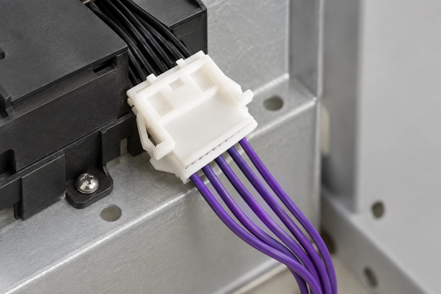
The preserved page image shows a small white multipole wire-to-board-style assembly with dark and purple wires. A photograph can support that limited visual description, but it cannot establish pitch, contact count, cavity numbering, terminal technology, electrical ratings, materials, applicable standards, or intended appliance. Even apparent symmetry can hide polarization, skipped cavities, or different terminal positions.
| Evidence available | What it can support | What it cannot safely support | Engineering decision |
|---|---|---|---|
| Series name only | Search and supplier conversation | Interchangeability, rating, pitch, or application | Do not release |
| Photograph | General form and visible wire exit | Pinout, cavity count, contact system, or dimensions | Use only for identification |
| Uncontrolled sample | Preliminary fit study | Revision status or production consistency | Quarantine as reference |
| Matched, revision-controlled drawing package | Interfaces, tolerances, part identities, and inspection points | Performance not backed by the specified tests | Proceed to validation |
A controlled interface definition prevents false matches
Start with the complete mating system, not one housing
Define the cable-side housing, terminals, locks, board-side header, and keying parts as one interface. Compare controlled dimensions with the PCB footprint and enclosure keep-out. ZUCH’s guides to small-pitch connectors, PCB headers, and the broader connector range provide category context; none substitutes for the PNIW drawing.
Make the pinout auditable from schematic to cavity
Create a cavity table that connects schematic net, wire identifier, wire color, cavity number, and board-header pin. Show the viewing direction on every drawing. Then verify the finished assembly electrically against that table; color alone is not a durable pinout control because approved alternates, lighting, and operator interpretation can change.

Verify the mate, coding, and latch as separate features
A successful insertion does not prove a correct mate. Record the exact mating part number, key orientation, latch engagement, terminal seating, and any connector-position assurance feature. Run a wrong-mate challenge against adjacent connectors used in the appliance. If an operator can insert the wrong plug without abnormal force, color coding is an aid, not the primary error-proofing control.
Define termination and strain relief from the real wire set
The terminal part number, conductor construction, strip length, tooling, and inspection method must be specified for each approved wire. Do not infer crimping, soldering, or insulation-displacement technology from the photo. Validate the finished wire-to-terminal joint and the harness-level bend path separately: a sound contact joint can still fail when an unsupported cable transfers pull or repeated flex directly into the rear of the housing.
A staged verification plan catches failures before line release
Compare documentation, inspect parts, then test assembled samples under intended conditions. Small geometrical differences can create intermittent contact, terminal back-out, assembly delay, or PCB damage. When faster edges are involved, consult this guide to small-pitch connector signal-integrity risks.
| Failure risk | Verification action | Evidencia a conservar | Release condition |
|---|---|---|---|
| Crossed or mirrored circuits | Continuity test from harness end to PCB net using the approved viewing direction | Pinout table and test record | Every circuit maps correctly |
| False mate or poor latch engagement | Fit check with the specified header plus a wrong-mate challenge | Mating-part IDs, photos, and inspection criteria | Correct mate locks; defined wrong mates are rejected |
| Terminal back-out | Inspect seating and apply the specified retention or wire-pull method | Method, sample size, force trace, and limit source | Results meet the drawing or qualified specification |
| Intermittent or resistive contact | Measure continuity or contact resistance before and after the chosen conditioning | Fixture, current, temperature, cycle count, and raw results | No interruption; values remain within the specified limit |
| Rear-entry fatigue | Exercise the actual routing, bend radius, clamp position, and service motion | Harness layout, conditioning record, and post-test inspection | No conductor, terminal, lock, or housing damage |
Illustrative total-cost check: compare the validated option’s added component and test cost with line-stop time + sorting labor + rework + scrapped boards + replacement freight + field service. Use the factory’s own rates and occurrence assumptions. A lower unit price is not a saving if unclear interfaces move inspection and failure costs downstream.
Standards define test scope but do not identify the PNIW part
IEC 60512 series: IEC 60512-1:2018 is a generic specification for connector tests and measurements. It explains preparation, testing, requirements, and documentation, and directs users to relevant parts of the series plus a detail product specification. Select only methods that match the failure risks and define specimen condition, severity, sequence, and limits; citing “IEC 60512” without those details is not a test plan.
IEC 60352 series, only when the termination falls within scope: the series addresses different solderless connection technologies. For example, IEC 60352-2:2024 covers specified crimped connections and wire ranges, but that scope does not prove that the pictured assembly uses crimp contacts. First confirm the actual termination on the drawing, then select the corresponding part and tooling controls.
UL 1977, where applicable: the active fourth edition covers certain single- and multipole component connectors factory assembled to copper or copper-alloy conductors or printed wiring boards for data, signal, control, and power applications within or between equipment. Applicability depends on the end product, ratings, construction, destination market, and evaluation scope. Verify the exact model and authorization record before using “UL certified,” “UL recognized,” or similar language.
These documents are standards or test-method frameworks, not proof that a particular PNIW connector passed. A defensible compliance file ties the exact part and revision to the relevant requirement, test method, result, issuer, date, and scope. Unsupported compliance wording can trigger customer rejection, retesting, or a change notice after tooling and inventory are committed.
Procurement should release the connector only after closing five evidence gaps
- Obtain controlled drawings for both halves, terminals, locks, PCB footprint, cavity numbering, and permitted wire set.
- Approve samples against measurable dimensions and functional criteria, not visual resemblance.
- Freeze the pinout, mating pair, termination process, coding scheme, and strain-relief arrangement in the BOM and work instructions.
- Record the applicable test methods, conditions, sample size, acceptance limits, and source of each limit.
- Require change notification for tooling, material, terminal, plating, cavity geometry, and production-location changes that can affect fit or performance.
When a drawing package is available, ZUCH can discuss connector and header options against the documented interface rather than treating “PNIW” as a self-sufficient specification. Any equivalence decision should remain conditional until dimensional, assembly, and performance evidence is complete.
Frequently asked questions about PNIW connectors
What does PNIW mean on a connector?
The acronym is not defined by an authoritative public connector source in the evidence reviewed for this article. It may be a supplier-specific series or catalog label. Ask the named supplier for the official series definition and controlled drawing instead of expanding it from search results.
Can two PNIW connectors from different suppliers be interchanged?
Not on the name alone. Confirm mating geometry, tolerances, cavity numbering, terminals, keying, latch behavior, PCB footprint, and validated performance for both parts. Record an approved cross only after sample and document review.
Can the connector pitch or contact count be determined from the photo?
No. Perspective, hidden features, and partial wire population make a photograph unreliable for those decisions. Use a dimensioned drawing and physical measurement plan.
Which tests should a PNIW connector pass?
The honest answer is that the application and failure risks determine the test plan. Typical verification may address fit, continuity, contact resistance, retention, durability, and environmental conditioning, but methods, severities, and limits must come from the approved product and end-equipment specifications.
Does an IEC or UL reference prove the connector is certified?
No. A test-method citation is not a product certificate, and a standard’s scope is not evidence of evaluation. Verify the exact part number, revision, report or authorization record, issuer, date, and covered ratings before making a compliance claim.
Authoritative references
- IEC 60512-1:2018 — Connectors for electrical and electronic equipment, tests and measurements, generic specification
- IEC 60352-2:2024 — Solderless crimped connections, requirements, test methods, and practical guidance
- UL 1977, Edition 4 — Component Connectors for Use in Data, Signal, Control and Power Applications
The practical rule is simple: the series name starts the search; the drawing, matched components, and test evidence finish the decision.
Have a PNIW drawing or sample that needs an engineering review? Contact ZUCH with the mating-part number, PCB layout, wire specification, target market, and operating conditions so the open interface questions can be resolved before quotation or release.