Rectangular Connector Pin Count: Balance Density, Routing, and Service Access
When a controls engineer in Suzhou reviewed a crowded machine interface, the first proposal was to increase contact density. The review changed direction after the team mapped cable exits, maintenance access, protective-earth needs, and reserved positions; the visible problem was packaging, but the root cause was an incomplete interface definition.
Resumen: Select a rectangular connector from the released contact assignment and mechanical envelope, not from a pin-count headline. Contact count does not establish current, voltage, pitch, contact type, keying, or suitability. HARTING’s Han-Modular information shows why modular housings and modules must be evaluated as a system, while IEC publication 59671 should be checked for the applicable requirements and edition. Build a contact budget, reserve only justified positions, and verify routing, bend space, mating access, segregation, and replacement strategy before releasing the interface.
Contents
Pin count identifies the number of intended positions in a connector interface. It does not, by itself, define pitch, contact type, keying, housing geometry, terminal system, current path, or suitability for a particular assembly.
Start with the controlled contact assignment and mating definition. This makes the selection discussion specific enough for engineering and purchasing to compare equivalent interfaces. For a related technical reference, see Rectangular Connector Locking: Compare Lever, Screw, and Clip Interfaces.
| Interface question |
Why it matters |
Record to review |
| How many positions are required? |
Connects the housing to the intended contact assignment |
Schematic and released pin map |
| What mates with the connector? |
Prevents an incorrect assumption about compatibility |
Mating drawing and keying definition |
| What space is available? |
Shows whether density creates packaging limits |
Envelope, routing, and access layout |
Balance density against the physical envelope
Increasing the number of positions may change the connector’s footprint, cable exit space, and space available for neighboring components. Review the actual enclosure or board envelope rather than choosing a denser layout solely to reduce the apparent connector count. For a related technical reference, see RAST Connectors on Appliance PCBs: Review Layout, Mating, and Retention.
The selected interface must also leave sufficient room for the assembly and inspection conditions defined by the program. Those conditions are specific to the released product and should remain under engineering control.
| Decision dimension |
Single-piece connector |
Modular connector |
Review question |
| Envelope |
One defined housing footprint and one mating outline |
Housing, frame, and module arrangement create the working envelope |
Does the installed outline clear covers, barriers, and adjacent parts? |
| Wire bend radius |
A common exit can simplify routing but may concentrate the bundle |
Different modules may require separate exits or bend zones |
Is the documented cable bend allowance maintained after termination? |
| Mating access |
One latch or retention operation can be straightforward to inspect |
Module layout and frame access must be available during mating |
Can a technician release and verify the interface with installed neighbors? |
| Segregation |
Separation depends on the contact arrangement and the approved design |
Modules can support a planned grouping, subject to the selected system |
Are power, signal, communication, earth, and spare functions assigned as intended? |
| Replacement strategy |
A replacement normally addresses one complete connector definition |
A failed module may be replaceable independently if the released system permits it |
What spare parts, tools, and revision controls are needed in service? |
Important: Connector selection requires application-specific evaluation; matching a position count or a catalogue outline does not prove that a connector is suitable for the finished assembly. Source: TE Connectivity connector resources.
Check mating orientation, keying, polarization, contact assignment, and connector retention against the controlled design. A multi-position housing can still be the wrong choice when those definitions differ from the intended interface.
Keep the pin map with the relevant drawing revision. It helps the team distinguish an unused position, a reserved position, and a contact that is part of the released electrical design.
The HARTING product reference 20 7000 11001 is an ordering reference to verify against current technical documentation; the number of positions still does not establish current or voltage. Use the applicable edition and scope of the IEC Webstore publication 59671 as part of the standards review.
Contact-budget worksheet and release checklist
Use this worksheet before selecting a housing. The assumptions are planning assumptions only: every listed position has one controlled function or an explicitly documented reserve; a spare is not automatically safe to populate; power and communication segregation follows the approved design; protective-earth positions are assigned by the responsible electrical engineer; and current, voltage, creepage, clearance, temperature, and conductor limits are verified separately from contact count.
| Function group |
Budget / assignment |
Assumption to record |
Release check |
| Power |
___ positions; circuit IDs ___ |
Separate power from other functions as the approved design requires; ratings come from selected contact and system evidence |
Confirm conductor, contact, spacing, protection, and test requirements without deriving them from count |
| Signal |
___ positions; I/O or sensor IDs ___ |
Record signal type and required separation or shielding assumptions |
Verify pin map, keying, noise-control measures, and inspection access |
| Communication |
___ positions; protocol / pair IDs ___ |
Record pair or shield arrangement, routing path, and any required segregation |
Check the selected system’s contact, cable, shielding, and mating documentation |
| Protective earth |
___ positions; PE IDs ___ |
Assignment and continuity requirements are controlled by the electrical design and applicable rules |
Verify termination, bonding, identification, and test evidence |
| Spare / reserved |
___ positions; future-use note ___ |
Reserved positions remain unassigned unless a controlled change releases them |
Mark cavities, sealing, documentation, and change-control treatment |
Worksheet total: required positions + protective-earth positions + documented spare positions = ______ positions. Add the housing, module, keying, routing, bend-radius, mating-access, segregation, and replacement constraints before approving the count.
Preserve routing and service access
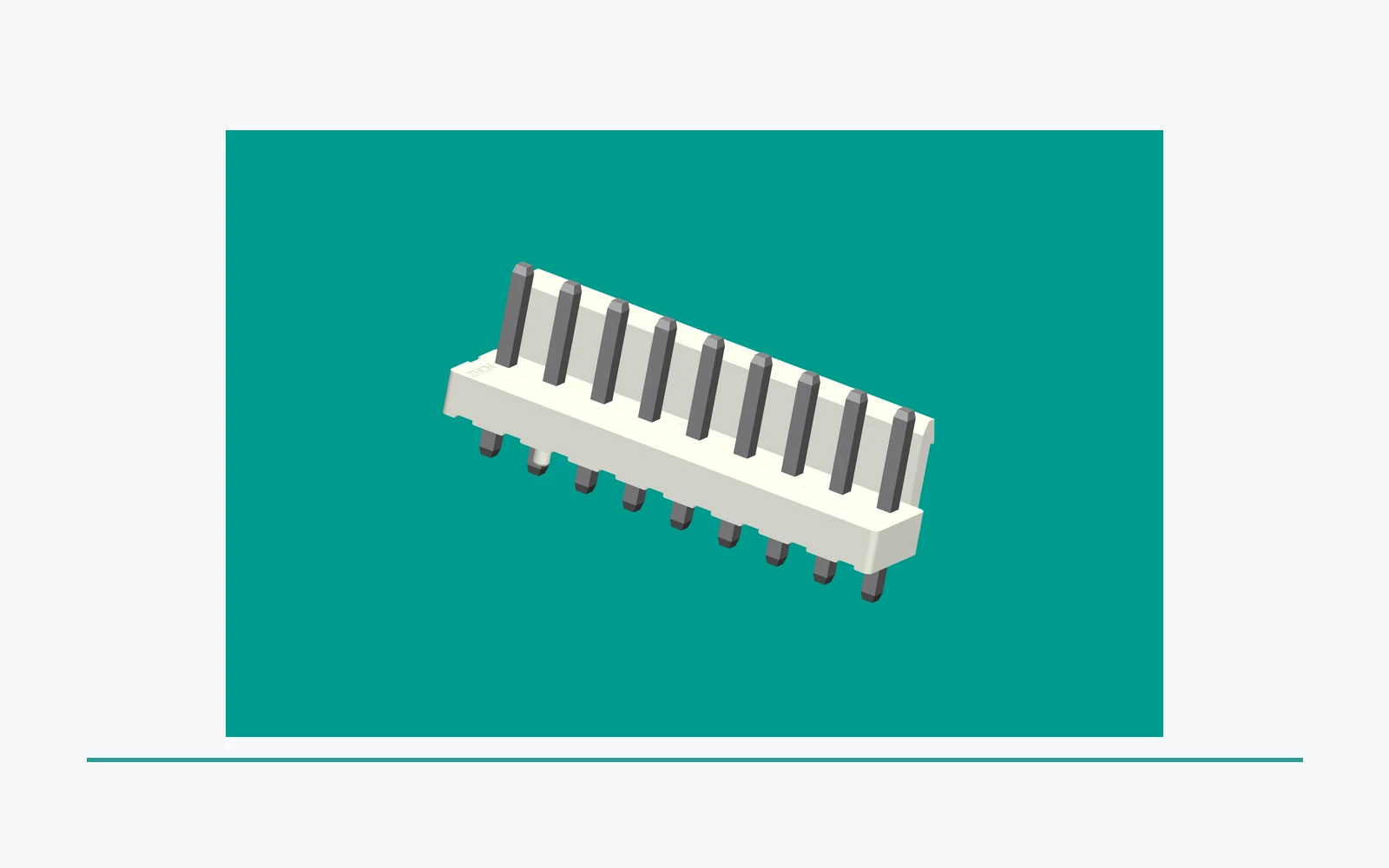
Dense connector layouts can affect wire break-out, bend space, latch access, tool clearance, and the ability to identify individual positions during assembly or service. Review these conditions in the complete assembly, including nearby covers, barriers, and harness supports.
Service access is not a cosmetic consideration. It can change whether the released design can be inspected, mated, retained, or replaced in the intended environment.
Build a complete selection record
Use the same controlled definition for engineering review and supplier communication. This avoids a response based only on a generic phrase such as “12-pin rectangular connector.”
| Selection record item |
Purpose |
Send with RFQ |
| Pin map and revision |
Defines the requested position count and assignment |
Schematic, connector drawing, and revision |
| Mating and keying data |
Confirms the required interface relationship |
Mating-part definition and keying view |
| Envelope and routing limits |
Exposes density and access constraints |
Board or enclosure layout, cable exit, and access notes |
| Evidence and change needs |
States what the program expects from a response |
Sample objective, records, and change-notice requirement |
Control revisions and proposed alternates
A change to pin count, keying, housing, terminal, contact assignment, mating part, or routing can affect the original interface review. Treat it as a documented change rather than assuming a connector with a similar number of positions is interchangeable.
When an alternate is suggested, compare it with the controlled revision and route differences to the responsible engineering process. The supplier response should identify what it addresses and what still needs program evaluation.
Start a controlled ZUCH rectangular-connector inquiry
ZUCH’s rectangular connectors route and product catalogue provide a commercial route for identifying connector families. They do not confirm fit, stock status, validation, certification, or approval for a specific application.
For a useful inquiry, include the released pin map, mating and keying information, mechanical envelope, routing and access limits, sample objective, requested records, and change-control requirements. Submit controlled documents through the sample request route or contact page.
FAQ
How many contacts should a rectangular connector have for a given control cabinet or machine interface?
Start with the released power, signal, communication, protective-earth, and documented spare positions, then map them to a compatible contact and housing system. The total must also fit the envelope, bend-radius, mating-access, segregation, and replacement requirements. Do not derive current or voltage from the count; verify those values from the selected contact system and application evidence.
Is a higher contact count always the most space-efficient solution once wiring and maintenance are considered?
No. A higher count can reduce the number of housings while increasing bundle concentration, bend-space demand, tool-clearance needs, or service complexity. Compare the installed envelope and maintenance task, not only the connector face.
Is a higher pin count always a better connector choice?
No. The selected position count must match the released contact assignment, mating definition, envelope, routing, and service requirements.
Does pin count alone define a rectangular connector?
No. Pitch, keying, contact system, housing geometry, mating interface, and application constraints also require review.
Why does service access matter in a dense connector?
It can affect latching, inspection, cable routing, tool clearance, and the ability to identify or service positions in the installed assembly.
Should spare positions be added without review?
No. Reserved positions can affect the controlled interface, housing, routing, and documentation. Review them with the responsible engineering team.
What should a connector drawing identify?
It should identify the controlled housing and mating interface, position count, pin assignment, keying, relevant dimensions, and application constraints.
Can an alternate connector be compared by position count?
Not reliably. Compare the complete controlled interface, including mating, keying, contact system, envelope, and required evidence.
What belongs in a rectangular connector RFQ?
Provide the current pin map and drawings, mating and keying definition, mechanical envelope, routing and service constraints, sample needs, requested records, and change-control expectations.
References
Conclusion
A rectangular connector is space-efficient only when its complete interface remains workable after wiring, mating, inspection, and replacement are considered. Start with a controlled contact budget that separates power, signal, communication, protective earth, and documented spare positions. Then test the single-piece and modular options against the installed envelope, cable bend radius, mating access, segregation plan, and replacement strategy. HARTING’s modular references and the IEC Webstore publication provide useful source points, but neither turns a contact count into a current, voltage, or compliance claim. ZUCH can review a defined inquiry when the pin map, drawings, routing limits, worksheet assumptions, and evidence request are supplied. The durable rule is simple: count positions only after you have defined the work each position must perform.
 Zhejiang ZUCH Technology Co., Ltd.