Zhejiang ZUCH Technology Co., Ltd.
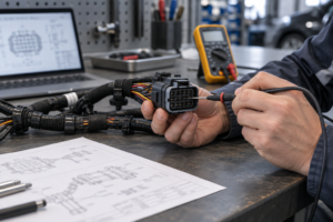
When a harness buyer in Birmingham encountered a failed sensor check in this hypothetical sourcing example, she compared the replacement connector with the purchase order. Both said “2-wire,” but the supplied housing would not latch onto the sensor. The first sample build stopped immediately. The problem was an incomplete interface specification: the wire count matched, while the mating geometry did not.
Summary: A 2-way automotive connector usually has two contact positions; a 2-wire connector describes a connection involving two conductors. They can describe the same assembly, but neither term alone proves compatibility, polarity or sealing. Specify the two mating interfaces, populated positions, terminals and wire details against a drawing before ordering.
These terms overlap in catalogues because many small harness connections use one wire in each of two positions. Automotive connection documentation, including ISO 8092-2, treats definitions, test methods and performance requirements separately from a seller’s shorthand. That distinction matters when purchasing housings, complete connector kits or prewired repair leads.
What do 2-way, 2-wire and 2-pin actually describe?
“Way” generally refers to an available contact position in the connector interface. A two-way housing normally provides two positions, but it may be supplied without terminals. “Wire” refers to the conductors in the harness or pigtail. A two-wire assembly might use a two-position housing, two individual single-position connections, or a larger housing with only two occupied positions.
“2-pin” is common search and catalogue language for a two-position connector. However, a precise parts list should distinguish pin contacts from socket contacts. A seller may call a socket-equipped assembly “2-pin” simply to describe its position count. Use the manufacturer’s drawing and bill of materials to settle the terminology; ISO 8092-2 provides a technical framework, not permission to treat all two-position products as interchangeable.
“2-cavity” usually describes a housing with two places where contacts could be installed, not proof that both places are populated. That housing may arrive empty, with one contact fitted, or as a completed two-contact assembly, depending on the supplier’s scope. “Mating pair” creates another possible mismatch: it may mean the two compatible housings only, while terminals, seals, secondary locks or leads remain separate items. The order should therefore state both the available position count and the populated contact count, then identify every included component.
| Description | What it usually counts | What it leaves unresolved | Buying check |
|---|---|---|---|
| 2-way housing | Two available contact positions | Terminal inclusion and occupied cavities | Request the housing drawing and supplied-parts list |
| 2-wire connector assembly | Two conductors | Housing size, contact type and circuit assignment | Request the assembly drawing and wire schedule |
| 2-pin connector | Often two positions; sometimes specifically pin contacts | Whether the listing uses “pin” literally | Confirm actual contact geometry |
| Two-position mating pair | Two positions across a matched interface | Whether terminals, seals and locks are included | Quote both halves and all assembly components |
A practical request therefore says more than “send a 2-wire automotive connector.” It identifies the mating part number or controlled interface drawing and states whether the buyer needs empty housings, loose components or terminated leads. This prevents quotes for different levels of assembly from appearing equivalent.
A practical ordering sequence is: first define whether the connection is wire-to-wire or wire-to-device; next freeze the two mating interfaces and their keying; then list each housing, pin or socket contact, seal and lock; finally record the conductor count, occupied cavity numbers and supplied assembly state. In that sequence, “2-way,” “2-pin” or “2-cavity” filters the housing, “two populated contacts” defines what is installed, and “2-wire” defines the harness conductors. A complete mating pair must be called out explicitly rather than inferred from any one of those labels.
Two positions do not necessarily mean two independent circuits
Catalogue “circuit count” sometimes means contact count. Electrically, two conductors can provide supply and return for one load, form a sensor connection, or carry a paired signal. They are not automatically two separately powered circuits. Likewise, two physical positions do not establish current capability, allowable voltage or signal suitability.
Write the function of each occupied position in the harness schedule. Do not assume that cavity 1 is positive, cavity 2 is negative, or that a visible wire colour supplies a universal answer. Those assignments come from the equipment schematic and connector view, not the number of ways.
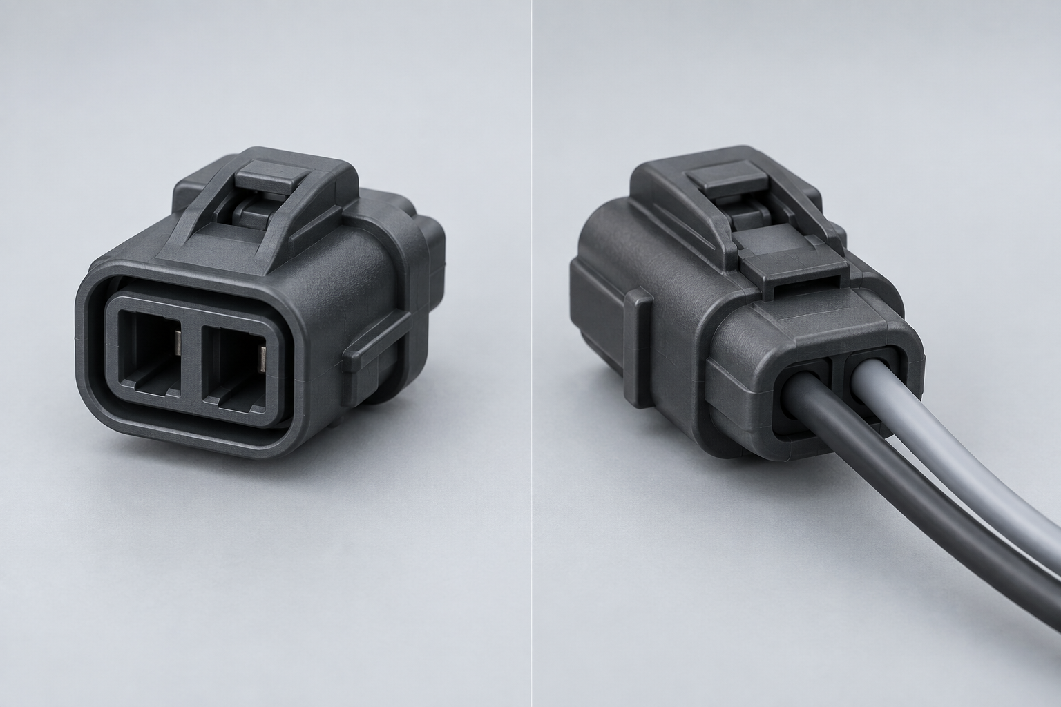
Why must the plug, socket and sensor interface be specified together?
Two connectors can each have two positions yet differ in keying, pitch, terminal geometry, latch shape and sealing arrangement. Matching the count is only an initial filter. A housing that appears to fit can still lack the correct contact engagement or retention. SAE/USCAR-2 addresses automotive connector-system performance; it does not create universal interchangeability between products with the same position count.
Separate the housing description from the contact description. Supplier conventions for “plug,” “receptacle,” “male” and “female” can vary, particularly when the outer housing shape differs from the gender of its contacts. State both housing part numbers and the pin or socket terminal part numbers. If one side is built into a sensor, use that sensor’s approved mating-connector documentation.
The broader arrangement of automotive electrical harness connectors also matters: an inline harness pair and a harness-to-device connection may require different mounting, routing and service provisions even when both use two conductors.
How does a wire-to-wire connection differ from a wire-to-device connection?
In a wire-to-wire topology, both halves normally terminate harness conductors, so the released definition must cover both housings, both terminal sets and whether the joint is free-hanging or fixed by a clip or bracket. In a wire-to-device or wire-to-sensor topology, the device-side interface may already be integrated into the component. The harness order may then require only the approved mating half, but it still has to match the device drawing.
Freeze four details before requesting samples: which half belongs to the harness, the actual pin-or-socket contact on that half, the keying and latch orientation, and the required mounting or strain-relief arrangement. Housing shape does not reliably establish terminal gender, and a correct terminal family does not correct the wrong key or mounting form. These details also determine whether a quoted “pair” contains an unnecessary device-side part or omits a required harness-side component.
What changes when the two wires belong to a sensor?
Start with the sensor interface specification. A passive resistive sensor, a passive inductive sensor and an active two-wire sensor do not necessarily use the same electrical method. Two wires may carry a measured resistance, an induced signal, or power and information through the same interface. Their count alone cannot identify the sensor technology.
Consequently, do not relabel every sensor pair “positive” and “negative.” Some applications require polarity control; others require attention to signal phase or the controller’s designated return. Shielding, twist and routing requirements must come from the device and vehicle documentation. The connector selection must preserve those requirements without inventing a third connection or changing the circuit.
| Application | Possible role of two conductors | Document to check | Important limitation |
|---|---|---|---|
| Simple DC load | Supply and return | Load schematic and operating requirements | Two positions do not establish load capability |
| Passive resistive sensor | Measurement connection and return | Sensor and controller interface documentation | Do not infer a chassis-ground connection |
| Passive inductive sensor | Signal pair | Sensor pinout and signal requirements | Follow specified orientation and routing |
| Active two-wire sensor | Device-specific power and signal interface | Exact sensor datasheet | Polarity and operating method are model dependent |
Can a two-wire connection be sealed and automotive qualified?
Yes, a two-wire assembly can be designed for environmental protection. The words “two-wire” and “two-way” provide no evidence of that protection. IEC 60529 classifies enclosure ingress protection; it does not assign a rating because a connector has a rubber seal or a particular number of positions.
For a sealed design, check the interface seal, individual wire seals where used, insulation-diameter range and any required cavity plugs. One conductor installed through an oversized seal can undermine the intended assembly. Ask whether the claimed protection applies when mated, unmated with a cap, or under another explicitly tested condition. Avoid replacing these conditions with the unqualified word “waterproof.”
Also distinguish environmental evidence from electrical and mechanical validation. A connection may need resistance, retention, temperature, vibration or other evaluations defined by the vehicle programme. Passing an ingress test does not establish suitability for every load or installation location.
- ISO 8092-2: covers definitions, test methods and general performance requirements for road-vehicle harness connections within its scope. Identify the applicable edition and requirements in the specification.
- SAE/USCAR-2: provides automotive electrical connector-system performance requirements and procedures. Request evidence for the relevant assembly and agreed application conditions.
- IEC 60529: defines IP classification and associated tests. The rating concerns the tested configuration, including the conditions relevant to that rating.
- IEC 60512: is a series of connector test methods. Select the relevant part and acceptance criteria; citing the series alone is not product certification.
None of these names proves that an unspecified product is certified or approved by a vehicle manufacturer. Procurement should connect each claim to a report, drawing revision and tested configuration. An unsupported claim can delay approval, trigger repeat testing or require replacement of an installed batch; destination-market and customer obligations must be checked separately.
How should buyers turn a two-way description into an orderable specification?
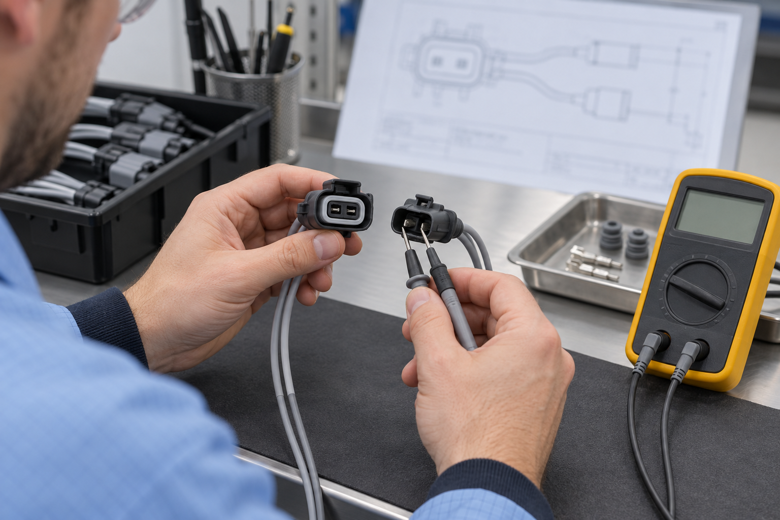
Use four checks to move from a search term to a controlled assembly. For a two-position connection, a two-row cavity schedule is short enough to review alongside the mating drawing. Where testing is specified, tie the plan to the relevant SAE/USCAR-2 requirements or selected IEC 60512 methods rather than a generic “tested” statement.
- Read the schematic. Record the function of each conductor, polarity or orientation requirements, and relevant electrical and environmental conditions.
- Match the interface. Confirm both mating parts, keying and cavity numbering. State whether the drawing shows the mating face or wire-entry face; viewing direction can reverse the apparent layout.
- Specify the assembly. List terminals, wire size and construction, insulation diameter, seals, locks and approved termination instructions. Distinguish included components from separately ordered items.
- Verify the sample. Review fit, contact retention, cavity assignment and the agreed electrical checks before release. Follow device-approved test procedures so attached electronics are not exposed to unsuitable test conditions.
What should you check when a two-position sample does not mate or test correctly?
- It will not mate: compare the key, latch, polarization and interface drawing; do not force the housings together.
- It mates but will not latch: confirm the exact mating-half part numbers and any secondary-lock position.
- A terminal backs out: check terminal family, insertion orientation, primary retention and secondary-lock engagement against the assembly instruction.
- The circuit result is wrong: compare the cavity map, viewing direction and populated positions with the schematic before changing polarity or rewiring.
- The seal fit looks wrong: verify the specified wire seal, insulation-diameter range and unused-cavity treatment for that configuration.
This is a release diagnostic, not a substitute for the connector manufacturer’s assembly instructions or the vehicle programme’s acceptance plan. Record the mismatch and drawing revision so a corrected sample can be checked against the same controlled evidence.
Can solder replace a specified crimp contact?
Not automatically. A crimp-contact system is defined around the specified terminal, compatible conductor range, preparation, applicator or hand tool, and inspection process. Adding solder or substituting a soldered termination can change the termination and strain transition, so it should not be treated as equivalent unless the connector or vehicle documentation explicitly permits and defines that process.
For production, release the terminal and tooling together with the applicable crimp settings and acceptance checks. For service work, follow the approved repair method for the exact connector and application; neither crimping nor soldering is universal repair advice. Where a controlled crimp is required, use the specified terminal, tool and process rather than improvising from the housing’s two-position description.
For repair work, follow the approved procedure for de-pinning automotive connectors and inspect the housing before reusing it. Then control the cavity assignment when re-pinning automotive connectors; a mechanically seated terminal can still occupy the wrong position.
Compare quotations at the same assembly level. A low housing price may exclude terminals, seals, tooling, crimping and inspection. Total acquisition cost also includes sample approval, assembly time, rejected parts and service access. There is no defensible universal saving percentage: calculate the difference from your actual quantities and processes.
For a ZUCH enquiry, provide the approved mating drawing and complete component list. Ask for confirmation of the proposed configuration and supporting documents before treating a catalogue description as a released substitute.
Frequently asked questions
Is a 2-way automotive connector the same as a 2-wire connector?
Often they describe the same assembled connection, but they count different things. “2-way” normally means two available contact positions; “2-wire” describes two conductors. Confirm the populated positions and mating interface before substituting one listing for another.
Does a 2-way connector always have two terminals?
No. A two-way housing can be sold empty, and an approved assembly may leave a position unused. Check the bill of materials and any requirements for sealing or blocking vacant positions.
What is the difference between a 2-pin and 2-wire connector?
“2-pin” commonly describes two contact positions, although “pin” can also identify the actual contact geometry. “2-wire” describes the conductors. Neither phrase specifies the complete mating pair, wire size or terminal arrangement.
How do I choose a 2-way connector for a sensor wire?
Identify the exact sensor and its approved mating interface, then check the circuit assignment and wire requirements. Match the terminals, keying, seals and environmental requirements to that documentation. Do not infer sensor type or polarity from the two-wire count.
Can a 2-wire automotive connector be waterproof?
It can provide specified ingress protection when correctly assembled and used under the tested conditions. Request the applicable IP rating, report and mating-state requirements. Wire seals, insulation dimensions and assembly quality remain part of that claim.
How do I identify the positive and negative wires in a 2-way connector?
Use the vehicle schematic, device pinout and cavity numbering with the stated viewing direction. Do not rely solely on colour, cavity number or connector shape. Some two-wire sensor connections are not a simple positive-and-negative supply pair, so follow the device’s approved verification procedure.
References
- ISO 8092-2:2023 — Road vehicles: connections for on-board electrical wiring harnesses
- SAE/USCAR-2 — Performance Specification for Automotive Electrical Connector Systems
- IEC 60529 — Degrees of protection provided by enclosures (IP Code)
- IEC 60512 series — Connector tests and measurements
The count starts the search; the documented interface determines the connection.
Explore the ZUCH product range and contact the team with your mating drawing, two-position cavity schedule and operating requirements to discuss the appropriate sourcing options.