Zhejiang ZUCH Technology Co., Ltd.
When a harness engineer in a vehicle service bay sees an intermittent sensor, actuator, or motor fault, the visible symptom may be a failed component. A closer inspection often finds a six-circuit connector that was misidentified, under-specified, poorly crimped, or repaired without preserving terminal position. The practical question is therefore not simply “which six-pin plug fits?” It is whether the housing, terminal system, wire range, locking features, environment, and circuit map match the application. This guide gives buyers, harness engineers, technicians, and distributors a repeatable path for selecting a replacement and deciding when one damaged wire can be repaired safely.
Summary: Choose a 6 wire automotive connector from the wiring diagram outward: confirm the six circuit functions, cavity numbering, terminal family, conductor size, current and temperature conditions, mating direction, and sealing needs before comparing housings. ISO 8092 covers road-vehicle low-voltage connector dimensions and test considerations, while USCAR-2 is commonly used to specify automotive connection-system performance. A matching cavity count alone does not prove compatibility. Photograph the original connector, verify each circuit with the service information, inspect the terminal crimp and lock, and replace the housing when heat, deformation, corrosion, or loss of retention has compromised the connection.
What should be confirmed before choosing a six-wire connector?
A six-wire assembly has six electrical paths, but it may use different functions: power and ground, paired signal circuits, a reference and return, motor outputs, or several low-current controls. The same cavity count can therefore describe very different connector systems. Start with the vehicle or equipment wiring diagram, the connector face view, and the terminal part information. Do not infer pinout from wire color alone; colors can change between model years, harness branches, or repair kits.
Record the following before ordering:
- Connector family, keying, latch style, cavity numbering, and mating orientation.
- Terminal type, contact plating specified by the drawing, conductor range, and insulation support.
- Whether the circuit is sealed, exposed to splash, routed near heat, or subject to vibration and service movement.
- Wire cross-section, insulation diameter, bend radius, and the required splice or overmold arrangement.
- Any secondary locks, cavity plugs, seals, CPA/TPA features, or polarization keys.
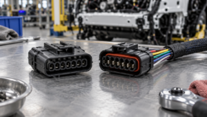
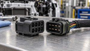
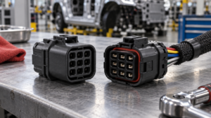
ZUCH’s connector product directory and rectangular connector category are useful starting points for comparing housings and connector families, but the final part number still needs to be checked against the drawing and harness specification.
How do connector type and circuit duty change the selection?
Connector selection is a system decision. A compact signal connector may be suitable for a sensor branch but unsuitable for a motor feed; a larger housing may provide space for a heavier terminal yet still fail if its lock, seal, or keying does not match the mating half. For that reason, a 6 wire automotive connector should be evaluated as a complete connection system. ISO 8092-2:2017 addresses low-voltage connections for road vehicles, including dimensional and test-related considerations. USCAR-2 provides a performance framework for automotive electrical connection systems; it is a specification used to evaluate a connection system under defined conditions, not a universal approval mark for every connector.
| Selection dimension | What to compare | Typical risk if ignored | Evidence to request |
|---|---|---|---|
| Interface and keying | Mating half, cavity layout, polarization, latch and secondary lock | Partial engagement, reversed position, or a connector that cannot lock | Connector drawing, face view, sample fit check |
| Terminal and wire | Contact family, conductor range, insulation support and crimp tooling | High resistance, terminal back-out, or conductor damage | Terminal datasheet, crimp specification, cross-section or pull-test record |
| Circuit duty | Current, voltage, switching, signal sensitivity and duty cycle | Heat rise, signal drop, nuisance faults, or accelerated wear | Electrical load definition and application test limits |
| Environment | Sealing, temperature exposure, fluids, vibration and service access | Corrosion, seal failure, fretting, or difficult maintenance | Environmental requirements and applicable validation plan |
| Service strategy | Depinning method, replacement terminals, repair space and traceability | Improvised repairs, repeat callbacks, or an unserviceable harness | Repair procedure, approved parts list and cavity map |
How can a six-wire connector be identified and wired correctly?
Use cavity numbers, not visual symmetry
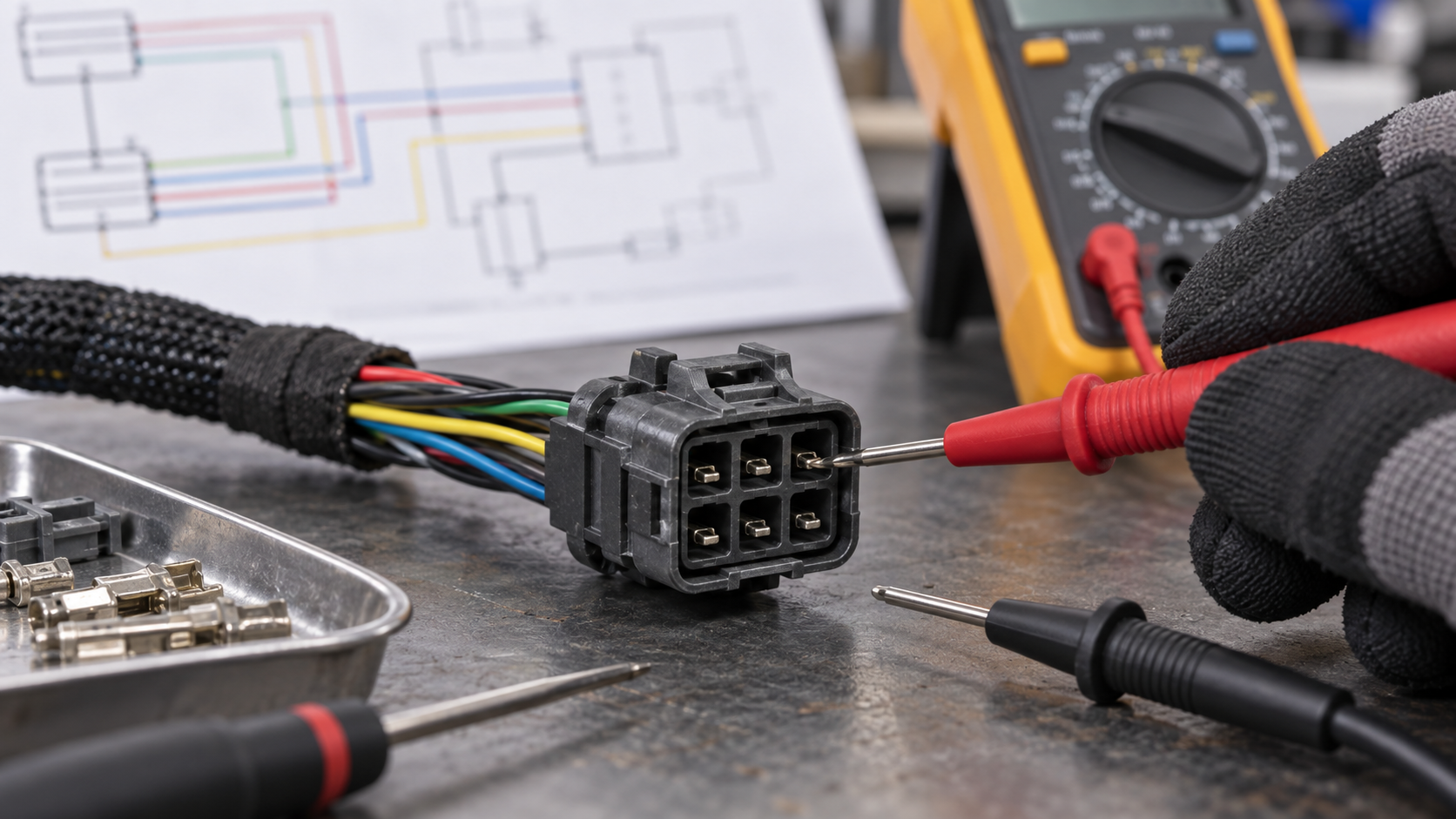
Identify the view shown in the service documentation: mating face, wire side, or terminal side. Mark cavity 1 and follow the manufacturer’s numbering direction. A connector can appear symmetrical when viewed from the wrong side, causing a mirrored pinout. Keep a photo of the original orientation and label each wire before depinning.
Map function, circuit, and terminal
Build a six-row map that links cavity number to circuit name, wire identification, terminal part, and destination. For a motor or compressor branch, distinguish supply and return from control or feedback circuits. For a sensor branch, identify reference, signal, and return circuits from the wiring diagram. Verify with a continuity or voltage test only under the vehicle maker’s safe test procedure; never probe a circuit in a way that spreads a sealed terminal.
Check the crimp before blaming the housing
A connector can look intact while a conductor is only partly captured by the terminal. Follow the approved crimp specification for strip length, conductor brush, insulation support, and tooling. ZUCH’s guide to crimping automotive terminals explains why the terminal and wire must be treated as one system. The related automotive connectors and terminals overview helps separate housing, terminal, and wire decisions when a replacement kit contains several parts.
Can one wire be repaired without replacing the entire connector?
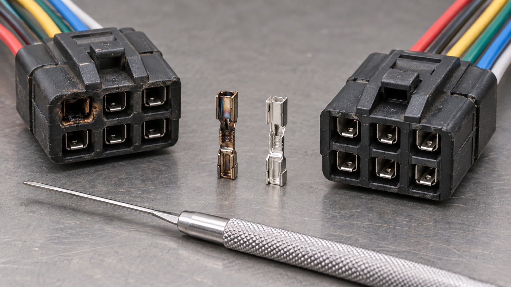
Often, yes, when the housing, lock, seals, and neighboring cavities remain sound and the replacement terminal is approved for that housing. A repairable 6 wire automotive connector still requires the original cavity map and terminal family to be preserved. Isolate power according to the repair manual, record the cavity, release the secondary lock, remove the terminal with the specified depinning method, and install a correctly sized terminal with the approved crimp. Confirm that the terminal’s retention lance engages and that the seal is not cut or displaced.
Do not splice by twisting and taping, move a wire to a visually convenient cavity, or mix terminals that have similar dimensions but different retention geometry. A repair should preserve conductor size, insulation support, bend relief, and the original circuit function. After reassembly, perform the manufacturer’s continuity, short-to-ground, and functional checks, then apply a gentle pull check that does not exceed the repair instruction.
| Step | Check | Pass condition | Stop and escalate when |
|---|---|---|---|
| 1. Isolate | Power state and system-specific safety procedure | Work can proceed under the vehicle maker’s instructions | Airbag, high-voltage, or other controlled circuit is involved |
| 2. Document | Connector orientation, cavity numbers, wire IDs and lock positions | Every wire can be returned to its original cavity | Numbering or face view is ambiguous |
| 3. Inspect | Housing, latch, seal, terminal spring and crimp barrel | No crack, burn, corrosion, spread contact, or back-out | Plastic is melted, lock cannot hold, or contact force is lost |
| 4. Repair | Approved terminal, wire size, strip length and tooling | Terminal locks and conductor is fully captured | Correct terminal or tooling cannot be identified |
| 5. Verify | Continuity, shorts, pinout and functional operation | Results match the service procedure | Intermittent fault remains or readings conflict with the diagram |
What causes a six-wire connector to lose continuity?
Common causes include terminal back-out, a relaxed contact spring, fretting or oxidation, moisture ingress, a cracked latch, an incomplete crimp, and wire fatigue at the strain-relief point. Vibration can make a marginal contact open only when the harness moves, so a static continuity check may pass while a wiggle test under the approved procedure reveals the fault. Heat can also discolor or deform plastic and increase contact resistance; the symptom then appears as a voltage drop or intermittent operation rather than a clean open circuit.
Use the wiring diagram to isolate the affected path and compare the suspect cavity with a known-good circuit where the test procedure permits it. Inspect both mating halves. Cleaning alone cannot restore a terminal that has lost spring force, and adding grease cannot correct a missing lock or incorrect crimp. Record the failure mode for purchasing and quality teams so repeat replacements do not reproduce the same terminal or routing error.
When should a six-wire connector be replaced?
Replace the housing and affected terminals when the plastic is burned, cracked, distorted, chemically damaged, or unable to retain the mating half. Replace terminals when contact beams are bent, plating is damaged, corrosion has entered the crimp, or the terminal backs out after insertion. If one cavity shows heat damage, inspect adjacent cavities and the load definition before selecting a higher-capacity substitute; a larger terminal is not automatically compatible with the original housing.
For procurement, ask for the complete connector system: housing, terminals, seals, cavity plugs, secondary locks, approved wire range, tooling, drawings, and validation records. ZUCH manufactures rectangular, RAST, FASTON, terminal, motor, and compressor connector lines and maintains IATF 16949:2016 quality-system certification, CNAS laboratory accreditation, and a UL witness laboratory; UL/CUL coverage and PA66/PA66 GWT material details apply where stated for the specific product. Request the applicable product evidence instead of treating a company-level credential as proof that every part meets every vehicle requirement.
Frequently asked questions
What is a 6-wire automotive connector used for?
A six-wire connector joins six circuits in a vehicle harness, such as power, ground, sensor reference and signal, actuator control, or motor-related conductors. The exact function depends on the wiring diagram and component. Confirm the cavity map and terminal family before selecting a replacement.
How do I identify wires in a 6-wire automotive connector?
Use the service diagram and the documented connector face view to map cavity numbers to circuit names. Confirm wire color, gauge, destination, and terminal position together; color by itself is not a reliable identification method. Photograph and label the connector before depinning.
Can I repair one wire in a 6-wire connector?
Usually, one wire can be repaired when the housing and locks are undamaged and an approved replacement terminal and wire are available. Follow the specified depinning and crimp procedure, preserve the original cavity, and complete continuity and functional checks. Escalate if the connector is heat-damaged, sealed components are compromised, or the circuit is safety-critical.
How do I match a 6-wire connector to a wiring diagram?
First establish whether the diagram shows the mating face or wire side, then align cavity 1 and follow its numbering direction. Match each cavity to circuit function, wire identification, terminal, and destination. Never mirror the layout based only on how the connector looks in your hand.
What causes a 6-wire connector to lose continuity?
Typical causes are terminal back-out, weakened contact force, corrosion or fretting, moisture, a poor crimp, wire fatigue, and a damaged latch. Test the complete path and inspect both mating halves, including the terminal and crimp. If the fault is intermittent, use the approved harness movement or vibration check.
Should I replace the connector if one terminal is burned?
Replace the burned terminal and housing when heat has deformed plastic, weakened retention, or affected adjacent cavities. Before fitting a new part, identify the load, crimp, contact resistance, and routing cause of the heat. A replacement with a different cavity or terminal system should be used only after the complete interface is requalified.
References
- ISO 8092, Road vehicles — Connections for on-board electrical wiring harnesses, International Organization for Standardization.
- USCAR-2, Performance Specification for Automotive Electrical Connection Systems, SAE International.
- IEC 61984, Connectors — Safety requirements and tests, International Electrotechnical Commission.
- ZUCH Technology public product and quality information, including connector families and stated certification scope.
Conclusion
The right six-wire connector is identified by the complete interface and circuit requirement, not by pin count or a housing that appears to fit. Start with the wiring diagram and cavity view; then confirm terminal geometry, conductor range, crimp method, environmental exposure, locking features, and service access. When one wire fails, repair it only if the housing, retention, seals, and neighboring cavities remain within specification. When heat, corrosion, deformation, or lost contact force is present, replace the affected connector system and investigate the cause before returning the vehicle to service. ISO 8092 and USCAR-2 provide useful reference frameworks, but the vehicle maker’s drawing and test procedure govern the repair. For documented connector options and application review, consult ZUCH’s product directory and contact the technical team with the cavity map, wire data, and mating-part information.