Zhejiang ZUCH Technology Co., Ltd.
A harness buyer approves a connector by cavity count and outline, only to discover during incoming inspection that the mating part is keyed differently—or that the same cavities carry different circuits in another vehicle. A technician faces the same risk when a familiar housing appears under the dashboard: one incorrect probe or jumper can damage a control module rather than confirm the fault. The reversal is important. The connector may be genuine and dimensionally correct; the failure comes from treating physical similarity as proof of wiring equivalence. This guide explains where interface standards do control geometry or defined diagnostic circuits, where vehicle documentation remains decisive, how drawing orientation changes the apparent numbering, and how to verify an unknown connection without guessing from color or shape.
Quick Answer: Most automotive connector pinouts are not universal. SAE J1962 and ISO 15031-3 define the 16-position diagnostic connector interface used for emissions-related vehicle communication, including specified contact positions, but that narrow case does not standardize arbitrary connectors throughout a vehicle. USCAR-2 evaluates electrical connector-system performance; it does not assign vehicle circuit functions to general cavities. For any automotive connector pinout, first match the exact housing, keying, and drawing revision; then confirm cavity numbers and viewing direction against the vehicle service wiring diagram. Use a controlled, power-off continuity check only as verification—not as a substitute for documentation.
Which Parts of an Automotive Pinout Are Standard, and Which Depend on the Vehicle?
A pinout combines two different kinds of information: a physical cavity reference and the electrical function assigned to that cavity. A component drawing may standardize or document the first. A vehicle manufacturer’s wiring information normally controls the second. Confusing these layers is why a connector that mates mechanically can still be electrically wrong.
Some interfaces do define both a connector arrangement and selected circuit positions for a particular purpose. The 16-position diagnostic link connector is the best-known example. SAE J1962 addresses the diagnostic connector, while ISO 15031-3 covers the diagnostic connector and related electrical circuits for emissions-related communication. Their scope is specific: neither document turns every 16-cavity housing into an OBD connector, nor do they create a universal scheme for door, lamp, sensor, powertrain, or appliance connectors.
By contrast, USCAR-2 is a performance specification for automotive electrical connector systems. Its tests help evaluate whether a connector system can withstand defined electrical, mechanical, and environmental stresses. They do not tell a harness designer that “cavity 4” must always be ground or that a terminal function transfers between vehicle platforms. Readers comparing these layers can also consult this overview of automotive connector standards.
Why Identical-Looking Housings Can Carry Different Circuits
Vehicle manufacturers can use one connector family across several model years, trim levels, engines, regions, or optional equipment packages. The housing may retain the same outer profile while the populated cavities, wire gauges, seals, terminals, or electrical functions change. A supplier may also offer multiple keys or polarization features within one family. Therefore, appearance and cavity count identify a candidate family, not a confirmed circuit map.
The business consequence is larger than the cost of a replacement plug. A wrong assignment can create harness rework, line stoppage, field returns, or damage to an electronic module. For procurement teams, the lower-total-cost approach is to control part number, key code, terminal system, revision, and approved drawing together with the vehicle-level circuit documentation.
How to Read Connector Cavities Without Reversing the Pinout
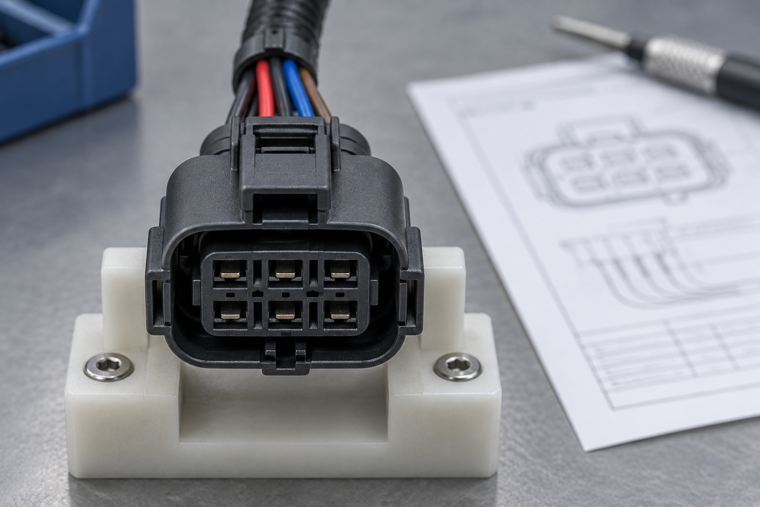
Many apparent pinout conflicts are orientation conflicts. A mating-face view looks into the connector where the two halves engage. A wire-side, harness-side, or rear view looks toward the cable entry. Turning the connector around mirrors the cavity pattern; a two-row layout that reads left to right from one side appears reversed from the other. A reliable drawing should state the viewing direction, show a datum such as the latch, key, or polarization feature, and identify cavity numbers.
Use the Molded Reference Before Counting Positions
Small molded cavity numbers may appear on the housing, although not every cavity is labeled and markings can be difficult to see. Start from a legible molded number, terminal-position-assurance feature, latch, or key, then follow the supplier drawing’s numbering sequence. Do not assume that numbering begins at the upper-left corner; that assumption changes with the view and the drawing convention.
Do Not Treat Pin, Cavity, and Circuit as the Same Thing
A cavity is a position in a housing. A pin or terminal is the conductive contact installed in that position. A circuit is the electrical function connected to the terminal. An unpopulated cavity has a location but no terminal; a populated terminal has no proven circuit function until the vehicle-level documentation identifies it. This distinction is especially useful when a drawing lists all housing positions but a particular harness populates only some automotive connector pins.
Before any electrical check, record the connector half, viewing side, latch orientation, key pattern, and cavity reference in a photo or worksheet. That short documentation step prevents the most common mirrored-numbering error and gives purchasing, quality, and service teams the same coordinate system.
Which Documents Can Confirm an Automotive Connector Pinout?
The safest hierarchy moves from part identity to vehicle function. First, identify the exact connector housing and revision from a manufacturer drawing or approved supplier specification. Second, confirm the keying, polarization, cavity numbering, and drawing view. Third, consult the service wiring diagram for the exact vehicle, model year, market, powertrain, and option set. Finally, use measurements to confirm a documented expectation. A guide to identifying automotive electrical connectors can help narrow the physical family, but family identification alone is not a pinout.
| Evidence or method | What it can establish | Main limitation | Decision value |
|---|---|---|---|
| Exact manufacturer drawing and part number | Housing identity, keying, cavity numbering, mating details, and specified terminals | Usually does not define the vehicle circuit assigned to every cavity | Primary evidence for component identity |
| Vehicle service wiring diagram for the exact configuration | Circuit functions, connector designators, splices, grounds, and module destinations | Wrong model year, market, or option package can change the map | Primary evidence for vehicle pin assignment |
| Molded cavity marks, latch, and key orientation | Physical reference needed to map the drawing to the connector | Marks may be partial, obscured, or read from the wrong side | Essential orientation control |
| Controlled power-off continuity or resistance check | Whether a conductor reaches a known endpoint under safe test conditions | Cannot by itself prove intended function; connected electronics can distort readings | Confirmation after documentation review |
| Wire color or online diagram without provenance | A clue for locating a possible circuit | Colors can repeat, change by build, or be shown inaccurately | Supporting evidence only |
A Safe Sequence for Verifying an Unknown Pinout
- Obtain the approved component drawing and the correct vehicle wiring documentation; confirm revision, market, and option applicability.
- Disconnect power according to the vehicle manufacturer’s service procedure and allow specified systems to discharge. Special handling may apply to high-voltage, restraint, pyrotechnic, and safety-related circuits.
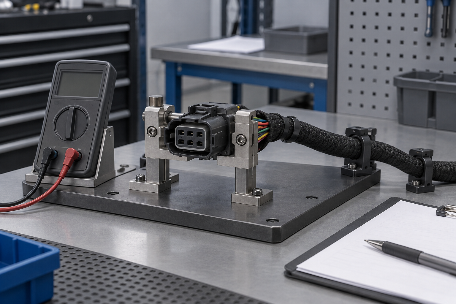
- Identify both endpoints before measuring. Use a high-impedance meter and approved breakout leads or back-probing methods that do not spread or deform the terminal.
- Perform a continuity or resistance check only on a de-energized circuit and only when the service procedure permits it. Never apply a test voltage or jumper to an unknown control-module, data-bus, airbag, or high-voltage circuit.
- Record the verified cavity, view, connector designator, circuit name, wire attributes, and document revision for traceability.
A powered voltage measurement may be part of an OEM diagnostic procedure, but it should not be improvised to discover an unknown pinout. If the circuit cannot be isolated or the documentation is uncertain, stop and obtain manufacturer or qualified service support.
Which Documents Should You Check Before Ordering a Connector?
The correct path depends on the decision being made. A buyer qualifying a connector family needs dimensional and terminal-system evidence. A harness engineer assigning circuits needs the controlled harness drawing and vehicle architecture. A service technician needs the exact wiring diagram and diagnostic procedure. Using one document for all three jobs creates avoidable gaps.
| Situation | First document or check | Supporting verification | Stop or escalate when |
|---|---|---|---|
| Sourcing a replacement housing | Exact supplier part number, key code, revision, and mating drawing | Terminal, seal, wire-range, and retention compatibility | The housing fits visually but keying or approved terminal data differs |
| Creating or revising a harness | Released harness schematic and connector control drawing | Design review against vehicle architecture and change control | A circuit assignment lacks an approved source or revision owner |
| Repairing a known vehicle circuit | OEM service information for model year, market, engine, and options | Cavity orientation and permitted diagnostic measurements | The connector designator or configuration does not match the vehicle |
| Investigating an unidentified connector | Physical identification without energizing or jumpering circuits | Trace to a known endpoint after safe isolation | Restraint, high-voltage, data, or module circuits may be involved |
| Assessing standard automotive connectors | Confirm which standard and interface family actually applies | Check the standard’s edition, scope, and manufacturer implementation | “Standard” is being used without a document number or application boundary |
How Performance, Application, and Wiring Documents Differ
Performance Specifications Describe Behavior, Not Circuit Assignment
USCAR-2, developed through the USCAR Electrical Wiring Component Applications Partnership, is concerned with automotive electrical connector-system performance. Its presence on a requirement list should lead buyers to ask which test sequence, revision, connector configuration, wire size, and acceptance evidence apply. It should not be interpreted as a universal cavity-function chart. A standard can define how a specimen is tested without certifying every product or assigning its vehicle circuits.
Manufacturer Specifications Define How the Connector System Is Used
A connector supplier’s drawing and application specification can define compatible housings, terminals, wire ranges, seals, keying, cavity numbering, assembly controls, crimp requirements, and sometimes test conditions. These documents determine whether automotive electrical connector pins are mechanically and electrically suitable for the chosen housing. They still do not replace the vehicle maker’s released circuit assignment.
Vehicle Wiring Documents Define the Installed Circuit Map
The vehicle wiring diagram or service manual links a connector designator and cavity to an actual circuit for a stated configuration. Applicability matters: model year, region, engine, trim, left- or right-hand drive, and optional equipment may change population or function. Procurement and repair records should preserve that configuration context rather than saving a cropped pinout image with no provenance.
SAE J1962 and ISO 15031-3 are narrower interface examples for diagnostic communication. Even there, the user must confirm that the subject is the designated diagnostic link connector and apply the correct document edition. Unsupported claims of “universal,” “standards-compliant,” or “direct replacement” can cause rejected parts, warranty disputes, unsafe repairs, and expensive revalidation.
Pinout Checks to Complete Before Buying a Replacement Connector
- Control identity as a set: record housing part number, keying, color where relevant, mating half, terminal family, seals, revision, and approved supplier—not cavity count alone.
- Require oriented drawings: every pinout or inspection sheet should name the connector half, show the latch or key, state “mating face” or “wire side,” and carry document revision control.
- Separate product qualification from circuit approval: performance evidence supports connector-system suitability; only released vehicle or harness documentation authorizes a circuit assignment.
- Plan non-destructive verification: use approved test adapters and service procedures so technicians do not deform terminals, pierce insulation unnecessarily, or energize an unknown circuit.
- Ask for application support: when sourcing a new family, require dimensional drawings, terminal application data, compatible tooling information, and traceable test documentation.
After these checks define the requirement, ZUCH can support connector sourcing discussions with configurable connector and terminal options, relevant product documentation, and an IATF 16949:2016 automotive quality-management framework. Buyers should still approve the exact part and pin assignment against their own released application documents. For broader component context, see this complete guide to automotive electrical connectors.
Frequently Asked Questions
Are automotive connector pin numbers the same across vehicle brands?
No. The same cavity number may carry different functions across brands, platforms, model years, or option packages. Use the exact connector drawing to locate the cavity and the correct vehicle wiring diagram to identify its circuit.
Do SAE, ISO, or USCAR standards define universal automotive pinouts?
No universal standard covers every connector in a vehicle. SAE J1962 and ISO 15031-3 define a particular diagnostic interface, while USCAR-2 addresses connector-system performance testing rather than assigning arbitrary vehicle circuit functions.
Why can identical-looking automotive connectors have different pin assignments?
A connector family can serve different trims, powertrains, regions, or model years, and its keying or populated cavities may vary. Visual similarity therefore confirms neither the exact part number nor the electrical function of each position.
Should a connector pinout be read from the mating face or the wire side?
Read it from the side explicitly stated on the drawing. Mating-face and wire-side views mirror the cavity layout, so confirm the connector half, latch or key position, and at least one molded cavity number before mapping any circuit.
How can I verify an unknown connector pinout without damaging vehicle electronics?
Begin with the exact manufacturer drawing and OEM service information, then isolate power according to the approved procedure. Use non-damaging breakout leads and a controlled continuity check only when the circuit is de-energized and the service procedure allows it; never jumper an unknown cavity.
Can wire colors be used to confirm an automotive connector pinout?
Wire color is supporting evidence, not proof. Colors can repeat within a harness or change with model year, supplier, market, or repair history, so confirm the cavity and circuit through controlled documentation and an appropriate measurement.
References
- SAE International, J1962_201509: Diagnostic Connector.
- SAE International, USCAR2-8: Performance Specification for Automotive Electrical Connector Systems.
- United States Council for Automotive Research, Electrical Wiring Component Applications Partnership (EWCAP).
- International Organization for Standardization, ISO 15031-3: Road vehicles—Communication between vehicle and external equipment for emissions-related diagnostics—Part 3: Diagnostic connector and related electrical circuits: Specification and use.
Conclusion
The decision rule is simple: standardized connector geometry or performance does not automatically mean a standardized circuit assignment. First confirm the applicable interface or connector family; next fix the viewing direction, key, cavity numbers, and revision; then match the exact vehicle configuration and verify only with an approved, controlled measurement. Never skip the wiring-document check merely because a housing fits or a wire color looks familiar—either shortcut can convert a service question into module damage or harness rework. Once the electrical boundary is documented, ZUCH can help procurement and engineering teams review suitable connector and terminal options through its product directory. Contact ZUCH with the mating requirements, terminal data, application environment, and controlled drawings to begin a traceable component discussion.