Zhejiang ZUCH Technology Co., Ltd.
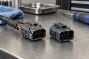
Selecting a sealing accessory often goes wrong before the connector reaches the assembly station. A buyer may match a seal to the conductor gauge, choose a plug that appears to fit an empty cavity, and assume a positive latch proves the assembly is protected. The visible result can be convincing at first, yet the connector may later admit moisture through an oversized seal bore, a damaged perimeter seal, an open cavity, contaminated sealing surfaces, or even a capillary path along the cable. The root cause is therefore not always a defective connector; it is often a mismatch among the connector family, wire insulation diameter, cavity condition, installation process, and required system test. This guide provides a practical way to specify, assemble, inspect, and replace each sealing component.
Quick Answer: Choose automotive connector seals from the exact connector-family documentation, using the finished wire insulation outside diameter—not wire gauge or seal color alone—as the sizing input. A wire seal closes the cable entry around an occupied cavity, an interface seal closes the housing-to-housing joint, and a cavity plug closes a designated unused cavity when the manufacturer requires one. Then confirm part numbers, assembly sequence, inspection criteria, and the test basis for the fully assembled connector. USCAR2-8 is a performance specification for relevant road-vehicle connector systems; it is not a universal size chart or a stand-alone product certification.
Match the Seal to the Wire and Connector Cavity
The first match is the connector family. Housing cavity geometry, terminal system, seal seat, and retention features are designed together, so a similarly shaped seal from another family cannot be assumed to fit. Start with the housing part number and revision, then use the manufacturer’s application specification, drawing, or approved accessory table to identify the compatible seal and terminal.
The second match is the finished insulation outside diameter (OD). Conductor gauge describes the metallic conductor, but the same gauge can have different insulation thicknesses, materials, and finished diameters. A seal selected only by AWG, metric conductor area, or color may be too loose to maintain contact or too tight to assemble without damage. Compare the actual cable specification—and, where the quality plan requires it, verified incoming dimensions—with the manufacturer-stated OD range for the exact seal.
The third match is the complete application condition. Temperature exposure, fluids, vibration, wire routing, mating frequency, repair policy, and the intended performance test all affect whether the specified connector system is suitable. Seal material or color must not be treated as proof of chemical compatibility or an ingress rating; those conclusions need product documentation and an assembled-system test basis.
- Identify the housing family, cavity, terminal, wire specification, and revision-controlled accessory part number.
- Verify finished insulation OD against the published seal range; do not convert from conductor gauge and stop there.
- Check whether the seal is loose, terminal-mounted, preassembled, or part of a multi-wire sealing system.
- Confirm the specified crimp tooling, insertion method, cavity-plug requirement, and final inspection criteria.
- Define the performance requirement for the assembled connection rather than assigning a rating to a loose seal.
What Wire Seals, Interface Seals, and Cavity Plugs Each Do
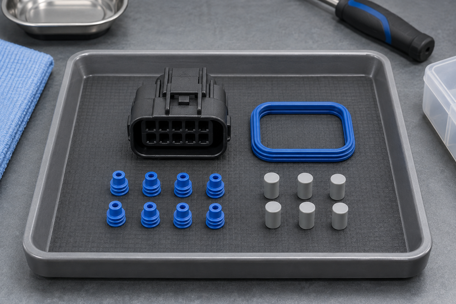
A sealed connection normally depends on more than one barrier. Individual wire seals address occupied cable entries, the interface or perimeter seal addresses the joint between mating housings, and automotive connector cavity plugs address specified unused entries. None of these parts automatically compensates for a missing, damaged, contaminated, or incorrectly seated part elsewhere in the system.
This distinction matters commercially because replacing the wrong component may not remove the leak path. It can also generate repeat disassembly, terminal damage, harness rework, diagnostic labor, and returns. For a broader discussion of ratings and test conditions, see the guide to watertight automotive electrical connectors.
| Component | Primary barrier location | Main selection inputs | Typical mismatch or damage | Cost consequence if misdiagnosed |
|---|---|---|---|---|
| Individual wire seal | Around the insulated wire at an occupied cable entry | Exact connector/terminal family, seal part number, and manufacturer-specified insulation OD range | Wrong OD range, nick, roll, incorrect seating, contaminated surface, or damaged wire insulation | Intermittent moisture entry, repeat terminal removal, and harness rework |
| Interface or perimeter seal | Between mating connector housings | Mating housing pair, seal design, orientation, condition, and assembly instruction | Pinch, twist, displacement, debris, housing damage, or incomplete mating | Replacing wire seals does not correct the actual housing-interface leak |
| Cavity plug | At a designated unpopulated cable entry | Connector family, cavity size, approved plug part number, and required seating position | Missing plug, wrong family, partial insertion, or use in the wrong cavity | A low-cost omitted part can create a direct leak path and a high-cost field diagnosis |
When does an empty cavity need a plug?
An unused cavity should be treated according to the connector manufacturer’s specified sealed configuration, not a shop-wide assumption. Some connector designs require an approved plug in every designated unpopulated cavity to complete the cable-side barrier. Other systems may use a different integrated sealing architecture. The housing drawing, application specification, approved bill of materials, or vehicle service documentation should therefore decide whether a plug is required and which plug is valid.
Installing a terminal later does not justify filling a cavity with an arbitrary temporary object. An improvised plug can deform a seal seat, leave a partial leak path, shed material, or interfere with future terminal insertion. Conversely, leaving a required cavity open because “the connector is latched” confuses mechanical mating with environmental sealing.
| Assembly situation | Evidence to verify | Preferred decision | Verification warning |
|---|---|---|---|
| Occupied cavity in new production | Housing, terminal, wire, and seal part numbers plus the stated insulation OD range | Use the approved combination and family-specific assembly process | A matching wire gauge does not prove a matching insulation OD |
| Unused cavity in a sealed configuration | Manufacturer drawing, application specification, or approved BOM | Install the specified cavity plug when the documented configuration requires it | Do not substitute by color, apparent fit, or a plug from another family |
| Service after terminal removal | Vehicle repair instruction and component-maker reuse criteria | Inspect all disturbed sealing surfaces and replace parts when damage or the instruction requires it | A seal can look present yet be cut, rolled, permanently deformed, or contaminated |
| Fully latched connector with water evidence | Leak-path inspection, wiring documentation, and the applicable assembled-system test | Diagnose the cable entries, unused cavities, interface seal, housings, wires, and remote capillary paths | Latch engagement verifies retention, not every sealing interface |
How to Install Seals and Plugs Without Creating a Leak Path
There is no safe universal sequence for every connector family. Some designs use loose single-wire seals, some use terminal-mounted seals, and others use preassembled or multi-wire seals. The current manufacturer application specification and the vehicle or harness work instruction must control the order, orientation, insertion depth, tooling, and any approved lubricant.
- Verify the controlled parts. Match the housing, terminal, wire, seal or plug, and revision before assembly.
- Inspect the sealing surfaces. Reject or escalate cuts, burrs, debris, distortion, damaged insulation, and questionable housing features under the applicable quality plan.
- Follow the family-specific wire preparation and crimp process. Do not let a generic stripping length, crimp profile, or tool setting override the manufacturer’s specification.
- Insert without forcing or improvised tools. Confirm the terminal and seal reach their specified positions and that any secondary lock is operated as documented.
- Close designated unused cavities correctly. Use only the approved plug and insertion method; a flush appearance alone may not prove correct seating.
- Mate clean interfaces and perform the required checks. Keep debris from the perimeter seal, complete all prescribed locking steps, and verify the assembled system using the applicable inspection or test plan.
During service, extraction tools and technique also matter because uncontrolled terminal removal can scrape a seal, damage a cavity, or deform retention features. The procedural overview on how to depin an automotive connector is a useful starting point, but the exact connector-family service instruction remains controlling.
Why can a fully latched connector still leak?
A latch primarily shows that the mating housings reached a mechanical retention condition. It does not independently verify every cable entry, empty cavity, sealing surface, or remote section of the wire. A connector can therefore be fully latched while moisture follows a different route.
- Wrong wire-to-seal relationship: the finished insulation OD is outside the approved range, or the insulation is nicked where the seal contacts it.
- Seal damage or displacement: a wire seal or interface seal is cut, rolled, pinched, contaminated, incorrectly oriented, or not seated as specified.
- Open unused entry: a required cavity plug is absent, incorrect, or partially installed.
- Housing or mating problem: damage, debris, or misassembly prevents the intended interface from forming even though the latch appears engaged.
- Capillary transport: fluid enters the cable at another location and travels along conductors or between cable layers toward the connector.
Troubleshooting should follow the path of the fluid rather than replacing every visible seal. Record where moisture first appears, inspect each barrier in sequence, review wire routing and upstream exposure, and use the specified test method for the assembled connector. Drying the connector or applying an unapproved compound may hide the symptom without resolving the source.
When should a disturbed seal be replaced rather than reused?
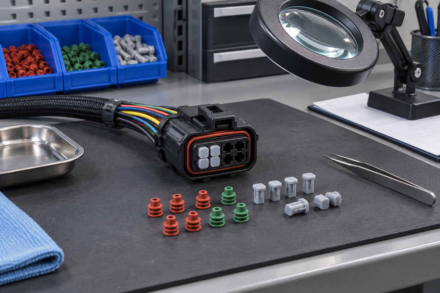
The default service decision should come from the connector manufacturer and vehicle repair documentation. Reuse should not be assumed simply because the seal remains on the wire. Removal can cut a sealing lip, roll the component, abrade its surface, drag contamination into the contact zone, or permanently change its shape.
Replace or escalate the part when it is nicked, torn, flattened, swollen, hardened, contaminated beyond the approved cleaning method, associated with damaged insulation, or identified as non-reusable in the applicable instruction. If reuse is explicitly permitted, inspect it under the stated acceptance criteria and reinstall it only with approved tools and materials. Unspecified grease, solvent, adhesive, or sealant can alter material behavior or obstruct inspection and should not be used as a generic repair.
Which Documents Should Be Used to Approve Seals and Plugs
Three document layers answer different questions. Treating them as interchangeable is a common source of overclaims and assembly errors.
Use Performance Specifications to Evaluate the Sealing System
USCAR2-8 covers performance testing for specified electrical terminals, connectors, and related components used in certain road-vehicle connection systems, including low-voltage systems from 0 to 20 VDC and coaxial applications within its stated scope. Its public abstract also says a component may not be represented as meeting USCAR requirements unless conformance to all applicable requirements has been verified and documented. It is a performance specification—not a universal product certification, seal-sizing chart, or proof that any single loose component will protect every assembly.
The IEC’s explanation of IP ratings describes a classification for protection provided by an enclosure under defined conditions. An IP claim must therefore be tied to the tested, documented configuration and relevant test basis. Calling loose parts, incomplete assemblies, or unverified sealed automotive connectors “waterproof” goes beyond the available evidence. The overview of automotive connector standards provides additional context on separating a test method from a product claim.
Use Manufacturer Specifications to Confirm the Compatible Build
The component manufacturer’s drawing and application specification should identify the connector family, compatible terminal and sealing accessories, insulation OD range, tooling, preparation, assembly, and inspection requirements. This layer answers which part fits and how it must be installed. A general industry performance specification cannot replace these family-specific instructions.
Use Vehicle Documents to Confirm Circuit and Service Constraints
The vehicle or equipment maker’s wiring diagrams, harness drawings, bills of material, repair manuals, and service bulletins determine circuit allocation, cavity usage, approved repair parts, routing, replacement boundaries, and verification steps for that application. This layer answers whether a cavity is intentionally unused, whether a repair is authorized, and which post-repair checks apply. Deviating from it can create miswiring, repeat leakage, warranty disputes, or unsupported compliance claims even when the individual components are genuine.
Final Checks Before Releasing the Seal and Plug Design
- Freeze the application identity. Record the connector family, housing pair, cavity count, terminal, wire specification, and document revision.
- Validate every sealing accessory. Map occupied cavities to approved wire seals and designated empty cavities to approved plugs where required.
- Review process evidence. Confirm crimp, insertion, locking, inspection, and repair instructions, including the approved tools and materials.
- Set claim boundaries. State environmental performance only for the verified assembled configuration and applicable test basis; do not convert a component description into a system rating.
- Plan change control. Recheck compatibility when the wire supplier, insulation construction, housing revision, seal, plug, terminal, or assembly process changes.
ZUCH can be considered at this document-review stage alongside other connector suppliers, but selection should still begin with the exact family and application evidence. Its public product directory allows buyers to identify relevant connector categories before requesting family-level drawings, compatibility information, samples, and quality documentation.
Frequently Asked Questions
How do I match an automotive wire seal to the wire insulation diameter?
Identify the exact connector and terminal family, obtain the manufacturer’s seal compatibility information, and compare the wire’s finished insulation OD with the specified range. Do not select by conductor gauge, color, or visual fit alone; verify the cable construction and revision before release.
What is the difference between a wire seal, an interface seal, and a cavity plug?
A wire seal closes around the insulated wire at an occupied cable entry. An interface seal closes the joint between mating housings, while a cavity plug closes a designated unused entry when the documented sealed configuration requires it.
Do all unused cavities in a sealed automotive connector need cavity plugs?
Not as a universal rule. Use the connector-family drawing, manufacturer application specification, approved BOM, or vehicle documentation to determine which empty cavities require which plug; never infer the answer from appearance alone.
Can automotive connector wire seals be reused after terminal removal?
Only when the applicable manufacturer and vehicle service instructions permit reuse and the seal meets their inspection criteria. Replace or escalate any seal that is cut, rolled, deformed, contaminated, chemically changed, or associated with damaged insulation.
Why can a fully latched connector still leak water?
The latch confirms mechanical engagement, not the integrity of every sealing path. Water may enter through a wrong-size or damaged wire seal, a displaced interface seal, a missing plug, contamination, housing damage, nicked insulation, misassembly, or a remote capillary path.
How should wire seals and cavity plugs be installed without damaging them?
Use the exact family-specific part, approved tool, orientation, preparation, insertion method, and inspection criteria. Keep sealing surfaces clean, avoid forcing components or applying unapproved chemicals, and verify the fully assembled connector under the specified process and test plan.
References
- TE Connectivity — Automotive Seals and Cavity Plugs.
- TE Connectivity — Product Page CAT-J58-NCP.
- SAE International — USCAR2-8, Performance Specification for Automotive Electrical Connector Systems, revised June 30, 2022.
- International Electrotechnical Commission — IP Ratings.
Conclusion
The sound decision rule is simple: treat every seal and plug as a connector-family component, not a generic accessory. First confirm the housing and terminal system; next match the finished insulation OD and the documented state of each occupied or empty cavity; then follow the controlled assembly sequence and verify the complete connection against the applicable performance requirement. Never skip the manufacturer’s application specification or convert a latch, component description, or isolated IP reference into proof that an assembly is waterproof. For buyers comparing waterproof automotive connectors, the defensible result comes from compatible parts, controlled installation, and documented system testing. Review the ZUCH connector product directory to identify a relevant family, then contact ZUCH with the wire OD, cavity plan, operating conditions, and required verification documents for a focused sourcing discussion.