Energy Storage Connector Creepage and Clearance: Design Rules for High Voltage
Use controlled application inputs and a representative validation plan before treating an interface choice as a release decision.
Contents
Begin with the controlled system architecture, intended voltage class, transient and pollution context, insulation concept, installation environment, and applicable standard selected by the program. IEC 60664-1 provides an insulation-coordination framework for low-voltage equipment within its stated scope; it does not replace the product or installation standard that governs a battery system. This guide does not supply a spacing value or compliance conclusion.
Design-input checklist: record the working voltage (including the waveform and whether AC, DC, or a mixed system), the expected overvoltage or transient category, the pollution degree and enclosure assumptions, the insulation material and its documented classification where required, and the installation altitude. Keep each value tied to the drawing revision and the standard or system requirement that supplied it. These inputs are screening evidence, not a universal distance table.
| Insulation-planning input |
Project record to provide |
Decision it supports |
| Live-conductor arrangement |
Relevant voltage domain, conductive parts, mating pair, and current drawing |
Identifies which separation paths need analysis |
| Insulation environment |
Pollution exposure, enclosure condition, altitude assumptions, and service state |
Establishes the design basis rather than a generic connector label |
| Verification plan |
Representative sample, measurement or test plan, acceptance record, and revision triggers |
Keeps evidence tied to the reviewed configuration |
| Electrical and environmental design inputs |
Working voltage, overvoltage/transient basis, pollution degree, insulation material evidence, and altitude |
Defines which insulation-coordination assessment and product requirements apply |
How should clearance be mapped?
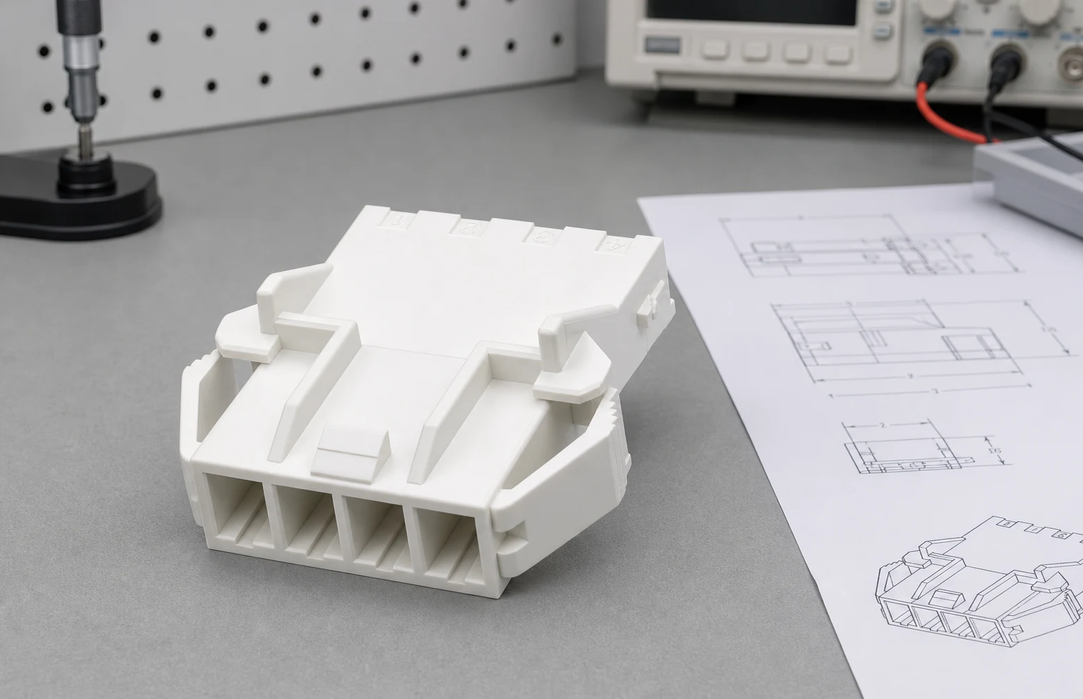
Clearance is the shortest distance through air between defined conductive parts under the governing design basis. Build a drawing-level map of terminals, busbars, housing features, fasteners, and adjacent assemblies so the program can identify the relevant shortest paths. Altitude, transient conditions, and the selected insulation-coordination method can change the assessment, so a catalog voltage label cannot establish an adequate air path by itself.
How should creepage be mapped?
Creepage follows the insulating surface between conductive parts. Surface geometry, contamination exposure, material characterization, mold parting lines, ribs, and assembly interfaces can all affect the path that must be evaluated under the selected requirements. Creepage, clearance, and solid insulation are related but different controls: clearance is an air path, creepage is a surface path, and solid insulation is the material barrier itself. A design review should identify all three rather than treating one measurement as a substitute for the others.

Why do materials and interfaces need separate review?
The plastic housing, seals, coatings, inserts, and adjacent structures are not interchangeable assumptions. Record the actual materials, their documented properties where required, and every interface that can alter the insulation path or environmental exposure.
| Material or interface question |
Evidence to review |
Selection limitation |
| Which insulating surfaces form the path? |
Housing geometry, rib details, insert locations, and the current drawing |
A nominal material name does not establish the finished path |
| What environmental conditions affect the interface? |
Program-defined exposure, conditioning, and installation assumptions |
Results need the stated conditions to be comparable |
| How are material or tooling changes handled? |
Change notice, revised sample plan, and reassessment trigger |
Final release remains with the responsible project team |
Important: Creepage and clearance are evaluated against the governing design basis and the stated configuration. A category-level description is not a spacing rule or a finished-system approval. (IEC Webstore) For a related technical reference, see Terminal Block Enclosure Design: Clearance, Creepage and Wire Entry Considerations.
What should the validation boundary include?
Specify the representative build, measurement method, environmental conditioning, dielectric or insulation evaluations only where the approved plan calls for them, acceptance criteria, safety controls, and change conditions. Do not transfer evidence from a different assembly.
How can an RFQ preserve the design intent?
Give suppliers the controlled drawing, mating arrangement, system context, material restrictions, environmental inputs, requested documentation, samples, and change-control expectations. Ask them to state open assumptions for engineering review.
Which ZUCH route supports a controlled inquiry?
For a component-category starting point, review ZUCH’s energy storage connector page with the product catalogue. The category can support early comparison, but the project still needs to establish actual insulation distances, configuration, and acceptance evidence. For a related technical reference, see Energy Storage Connector Anti-Mis-Mating Design for Battery Racks.
RFQ inputs
- Current drawing, mating arrangement, voltage-domain context, and intended assembly location.
- Pollution, enclosure, installation, service, and environmental assumptions used by the project.
- Requested material evidence, representative samples, insulation-review method, and acceptance path.
- Revision notification, substitution controls, documentation needs, and nonconformance process.
Fit Boundary
This guide supports a bounded engineering and sourcing discussion. It organizes the inputs that must be reviewed, rather than releasing a finished design. Submit configuration details through ZUCH’s sample request page or contact channel for a controlled component discussion.
FAQ
What is the difference between creepage and clearance?
Clearance is the shortest air distance; creepage is the path along an insulating surface. Both require evaluation against the applicable design basis.
Can a generic connector spacing be used for an energy storage system?
No. The required evaluation depends on the actual system, environment, insulation coordination approach, and applicable requirements.
Do plastics affect creepage evaluation?
Yes. The relevant material and surface configuration are design inputs that must be considered under the selected program requirements.
Does this article give high-voltage spacing values?
No. Values must come from the governing standard and controlled application inputs, reviewed by the responsible engineering function.
What should be included in a connector RFQ?
Include drawings, mating interfaces, system context, environmental conditions, material restrictions, validation requests, sample needs, and record requirements.
Can a catalog route prove compliance?
No. A catalog route supports product discovery only; compliance and approval require configuration-specific evidence.
What determines the required creepage and clearance distances in a battery-rack connector?
The controlled working voltage, overvoltage or transient basis, pollution degree, insulation material and construction, altitude, accessible conductive parts, and the applicable product or installation standard determine the design basis. The final distances must be calculated and verified for the actual configuration.
Can a connector’s voltage rating alone establish that its insulation spacing is adequate?
No. A voltage rating is one piece of product information and may be based on a defined test or application assumption. It does not, by itself, disclose the system overvoltage, pollution, altitude, material, mating geometry, or installation conditions needed to judge clearance, creepage, and solid insulation.
References
Conclusion
A battery-rack connector does not earn an adequate insulation decision from a nominal voltage label or a generic spacing rule. Start with traceable working-voltage and overvoltage inputs, then document pollution degree, altitude, material evidence, geometry, and the applicable product standard. Map clearance through air, creepage along surfaces, and solid insulation as separate but connected controls. IEC 60664-1 can inform insulation coordination within its stated scope, while related parts and the product standard may address specific protection methods or application conditions. Use the controlled drawing, representative samples, and a recorded verification plan to close assumptions. This evidence-led process gives design, sourcing, and supplier teams a common basis for an RFQ without implying a finished compliance approval.
 Zhejiang ZUCH Technology Co., Ltd.