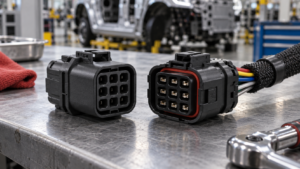
Energy Storage Connector Anti-Mis-Mating Design for Battery Racks
Use controlled application inputs and a representative validation plan before treating an interface choice as a release decision.
Contents
Part 1. What mis-mating risks should the design team define?
List the interfaces that could be confused during manufacture, service, rack integration, or replacement. Include adjacent connector families, similar circuit roles, cable lengths, orientation, access, human factors, and the consequences that the system design must prevent or detect. For a related technical reference, see Quick-Connectors for Serviceable Assemblies: Review Access and Replacement Inputs.
| Mis-mating control input |
Project record to provide |
Decision it supports |
| Confusable interface set |
Each mating pair, circuit role, physical location, and current drawing |
Shows where an incorrect connection could occur |
| Assembly and service view |
Operator access, orientation, cable reach, lighting, labels, and sequence |
Tests whether the controls remain usable in the rack |
| Error-control evidence |
Representative mock-up, work instruction, inspection step, and escalation trigger |
Connects the design control to an actual assembly process |
Part 2. How do mechanical keys support the interface?
Polarization, coding, shell geometry, latch direction, and mating envelope can help distinguish intended interfaces. Capture the exact mating pair and tolerance stack in the controlled drawing; a key concept alone does not prove error prevention in the assembled rack.
Part 3. Where do visual and documentation cues help?
Labels, color, connector position, harness identification, and work instructions can reduce ambiguity when they are readable in the actual installation condition. They should complement, not replace, the mechanical and electrical controls chosen for the program.

Part 4. Why should adjacent interfaces be reviewed together?
A connector may appear distinct in isolation yet become confusing among nearby modules, service loops, or similar housings. Review reach, line of sight, mating sequence, cable dressing, and maintenance access with representative hardware or a controlled mock-up.
| Adjacent-interface question |
Evidence to inspect |
Remaining project decision |
| Can neighbouring connectors be distinguished during service? |
Rack layout, connector positions, cable routes, and line-of-sight review |
The category page cannot prove serviceability in a specific rack |
| Does the intended key prevent the wrong pairing? |
Exact mating pair, orientation, tolerance stack, and controlled mock-up |
A key alone is not a complete error-proofing result |
| What changes require a repeat review? |
Label, housing, harness, layout, and alternate-source change triggers |
The project team defines final acceptance and release |
Important: A key, a label, or a color cue is not proof that a rack is mistake-proof. The representative layout, mating pair, service process, and program acceptance criteria must be reviewed together. (IEC Webstore)
Part 5. What belongs in anti-mis-mating validation?
Define realistic assembly and service scenarios, representative samples, observers or test instructions, inspection criteria, error handling, and records. Include only the tests and acceptance limits that the program has approved for the specific configuration.
Part 6. How should change control protect the result?
Changes to housings, labels, cable routing, mating parts, rack layout, or work instructions can change the human and mechanical interface. Establish a review trigger before substitution, tooling revision, or alternate-source introduction.
Part 7. Which ZUCH route supports a controlled inquiry?
To begin a component-category conversation, review ZUCH’s energy storage connector page and the product catalogue. The available category information does not replace an assessment of the actual rack, harness, mating pair, or service procedure. For a related technical reference, see Energy Storage Connector Creepage and Clearance: Design Rules for High Voltage.
RFQ inputs
- Current mating definition, connector locations, circuit roles, and drawing revisions.
- Rack layout, harness routing, access constraints, service sequence, and visible identification method.
- Mock-up or sample requirements, inspection instructions, error-handling process, and acceptance criteria.
- Change-notification expectations for housings, labels, cabling, alternate sources, and work instructions.
Fit Boundary
This guide supports a bounded engineering and sourcing discussion. It helps organize the interface risks that need review; it does not approve a finished battery rack. Submit configuration details through ZUCH’s sample request page or contact channel when a controlled component discussion is needed.
FAQ
What is anti-mis-mating design?
It is the set of controlled mechanical, visual, procedural, and system-level measures used to reduce the risk of connecting an interface incorrectly.
Are color codes sufficient to prevent wrong mating?
No. Color can support identification, but the full interface should be assessed with mechanical, routing, documentation, and validation controls.
What should a battery rack review include?
Review adjacent interfaces, orientation, access, cable reach, service sequence, identification, and the representative rack configuration.
Can a keyed housing prove an assembly is mistake-proof?
No. It is one control that needs evaluation with the exact mating parts, tolerances, work process, and system context.
What RFQ inputs help control anti-mis-mating?
Provide drawings, connector and mating-part definitions, rack layout, cable routing, identification scheme, validation requests, samples, and change-control expectations.
Does this guide approve a ZUCH connector for a battery rack?
No. It provides a discovery and RFQ framework; the responsible program must verify fit, validation, and approval.
References
 Zhejiang ZUCH Technology Co., Ltd.