Zhejiang ZUCH Technology Co., Ltd.
When a manufacturing engineer in Manchester encountered intermittent resets while releasing a connected countertop appliance, she traced the failure to a harness connector that looked fully seated after final assembly. A quick enclosure-open test showed a visible brown-out at load transition; the reversal came when the team found an underspecified wire range, inconsistent crimp-height control, and no documented mating check—not a simply “bad” connector.
Summary: Safe connector readiness starts before installation: isolate power, follow the equipment maker’s instructions, and assign mains-voltage work to qualified personnel. A smart home power connector must be selected as a system—wire, terminal, housing, strain relief, environment, and validation plan—not as a catalog line item. IEC 61984 addresses connector safety and performance requirements, while IEC 60512 supplies test methods; procurement teams should therefore require a documented application fit and test evidence before pilot build.
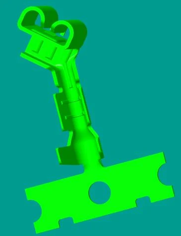
Smart-home and appliance hardware mixes low-voltage sensing with power paths that may originate at a mains supply or approved external power unit. The connector decision affects safety review, yield, service, and change control; it does not replace the OEM’s electrical design or jurisdiction-specific compliance assessment.
How should the power path be mapped before selecting the interface?
Start with a controlled power-path drawing: source, protective devices, conversion stage, loads, wire lengths, branches, and accessible service points. In many destination markets, nominal mains supply is 120 V or 230 V at 50/60 Hz; that is a design context, not a default connector rating. The responsible engineer must define voltage, current, conductor size, temperature, pollution degree, touch accessibility, and abnormal-use conditions from the finished-product requirements. Treat the power connector as part of this path, including the board and termination conditions when a PCB power connector is used.
For every smart home power connector location, separate functional signals from the power circuit and identify whether incorrect mating can create a hazardous condition. IEC 60512 test methods can support a verification plan with contact-resistance, insulation-resistance, voltage-withstand, mechanical-operation, vibration, and temperature-rise evaluations. The exact test sequence, sample size, and acceptance limits should come from the applicable product standard, connector documentation, and risk assessment—not from an assumed generic recipe.
Where should the boundary between field work and factory work be drawn?
Factory harness assembly is a controlled production process; field connection may be an installation activity governed by local rules and the OEM manual. For equipment tied to mains voltage, power must be isolated and absence of voltage verified by qualified personnel using approved procedures. The same documentation-first rule applies to a nest power connector installation in a proprietary smart-home accessory. A sourcing specification should state whether the connector is internal, user-inaccessible, serviceable, or intended for an authorized installer, because that boundary changes the enclosure, interlock, labeling, and documentation needs.
How should a rectangular interface be planned as a repeatable production process?
A rectangular power connector installation should begin with the approved harness drawing and connector family data, then proceed through controlled termination, keying confirmation, insertion verification, and final inspection. Rectangular formats can organize multiple circuits in a compact interface, but the housing alone does not establish creepage, clearance, current capacity, retention, or environmental suitability. Those characteristics depend on the complete configured assembly.
Before a rectangular power connector installation reaches the line, confirm terminal-to-wire compatibility, strip-length window, crimp-tool and applicator approval, conductor insulation diameter, cavity assignment, polarisation, and strain-relief routing. A first-article build should include visual inspection and pull-force or crimp-quality checks appropriate to the terminal supplier’s documented process. This is where a simple digital work instruction, a keyed fixture, and a traceable lot record can prevent a high-cost end-of-line failure.
How can mating force and retention become measurable evidence?
Test planning should cover expected mating cycles, cable movement, vibration, thermal exposure, and contamination. Mating-cycle durability matters most for serviceable modules; permanently assembled harnesses may place greater emphasis on retention and process repeatability. IEC 60512 methods support this work but do not approve the finished appliance.
How do termination controls and engineering changes affect installation quality?
Most installation escapes occur at interfaces: a similar-looking terminal, an unapproved crimp die, a wire substitution, or a late enclosure change. Establish one released bill of materials, a photo-supported cavity map, and a deviation workflow. A pilot lot may use 100% visual confirmation for critical cavities; the enduring inspection level should follow process capability and risk.
Document torque or retention only where the design calls for it; do not replace terminal-specific instructions with a general rule. Installation personnel should not work on energized conductors. Preserve traceability to the connector, terminal, wire, tool, operator training, and test record.
Which connector approach minimizes application risk and lifecycle cost?
A connector with a lower initial piece price can raise total cost when it complicates assembly, needs more rework, or produces ambiguous service diagnostics. The comparison below is qualitative; it helps teams frame an application review rather than declare interchangeable products compatible.
| Decision dimension | Configured rectangular interface | Single-circuit terminal approach | Board-mounted power interface |
|---|---|---|---|
| Typical fit | Multi-circuit appliance harnesses | Simple point-to-point internal wiring | Power transition at a PCB boundary |
| Assembly control | Keying and cavity maps can support poka-yoke | Requires clear terminal identification and insulation control | Requires PCB, solder, and mating-interface coordination |
| Serviceability | Can support controlled module replacement | May be compact but less obvious to diagnose | Depends on board access and connector retention |
| Unit-cost tendency | More elements; potentially lower assembly-error cost | Fewer parts; process variation can dominate | May shift cost into PCB design and validation |
| TCO question | Are rework and mis-mating risks reduced? | Are handling and inspection adequate? | Can board rework and thermal limits be managed? |
For a smart home power connector, hidden cost includes change review, approved tooling, training, inspection, failure analysis, returns exposure, and service labor. Illustratively—not predictively—preventing a repeated assembly escape can avoid combined rework, screening, and field-handling cost. Use the manufacturer’s own defect, labor, and warranty data.
How should application conditions determine validation effort?
| Application or cost driver | What to specify | Evidence to request | Why it affects cost |
|---|---|---|---|
| Heated appliance compartment | Operating and abnormal temperature envelope | Temperature-rise and material data for the configuration | May require additional validation and heat-management changes |
| Vibration or compressor-adjacent routing | Cable support, locking feature, and motion profile | Retention and vibration test plan using relevant IEC 60512 methods | Reduces investigation and service risk |
| High-volume harness line | Wire range, terminal, tooling, inspection points | Tool approval, crimp-process data, and traceability plan | Controls scrap, rework, and training burden |
| Regional product launch | Destination-market electrical and marking requirements | Compliance file mapped to the finished product | Avoids unsupported claims and delayed release |
Which standards claims can be made about the connector and which require appliance evidence?
IEC 61984 concerns safety requirements and tests for connectors; applicability must be confirmed against the actual connector and intended use. IEC 60512 is a series of test methods for electromechanical components, so citing it describes how a property may be tested rather than certifying a product. UL 1977 covers component connectors for use in data, signal, control, and power applications; recognition is component-level and does not automatically establish compliance of the complete appliance or system.
IATF 16949:2016 is a quality-management-system standard for organizations in the automotive supply chain; it is not a connector performance approval. Destination market, product category, accessibility, and marketing claims determine the evidence needed. Unsupported ratings, approvals, compatibility, or end-product claims create regulatory and commercial exposure.
What should a procurement-ready installation package contain?
- Freeze the electrical, environmental, mechanical, and service conditions in a revision-controlled application specification.
- Request the connector, terminal, wire-range, tooling, and test documentation as a matched configuration rather than mixing similar parts.
- Approve a rectangular power connector installation only after pilot-build evidence shows correct cavity assignment, termination quality, retention, and functional operation in the intended assembly.
- Define substitutions and engineering changes as controlled events, with revalidation proportional to their impact.
For OEM teams evaluating configurable harness interfaces, ZUCH can be considered as a connector-system source alongside the buyer’s qualification plan. Its portfolio includes rectangular connectors, RAST connector systems, terminals, and appliance-oriented connector families. The supplier states qualifications including IATF 16949:2016, a CNAS-recognized laboratory, and a UL Witness Lab; buyers should verify scope and program relevance.
What installation evidence distinguishes a safe pilot from a production-ready release?
A pilot proves that a team can assemble one sample; a production release must show that the released configuration is repeatable and appropriate for the finished appliance. The evidence should connect the drawing, terminal and wire combination, tooling, enclosure routing, locking state and test results to the same revision.
- Verify the de-energized assembly. Check cavity assignment, polarity, keying, latch engagement, secondary retention and cable support before applying power.
- Exercise the real conditions. Assess heat sources, compressor or motor vibration, condensation, cleaning exposure, service access and the number of expected mate/unmate operations.
- Record process evidence. Retain tooling setup, inspection points, sample identity, test methods, acceptance criteria and operator or supplier change control.
- Close the appliance file. Map connector evidence to the applicable end-product requirements; a connector standard alone cannot close the whole-appliance compliance case.
This distinction gives procurement a practical answer to “is the connector ready?” without confusing a first fit check with a released product validation.
What separates a pilot installation from a production release?
Use the release gate to identify which evidence is still missing before volume assembly.
| Review point | Record or question | Why it closes risk |
|---|---|---|
| Work instruction | Polarity, cavity, mating, locking, routing and inspection sequence | Turns one successful sample into a repeatable process |
| Assembly evidence | Tooling, wire/terminal compatibility, first-off and inspection records | Shows that the intended connection can be reproduced |
| Application validation | Enclosure, load, temperature, vibration and service conditions | Connects component evidence to the appliance |
| Change control | Part, wire, tool, supplier and drawing revision triggers | Prevents silent drift after release |
FAQ: How should a power-connector installation move from pilot to release?
How does a Nest Power Connector work in a heating-only system?
A proprietary accessory uses its own defined mechanical, electrical, and software ecosystem; its connector function cannot be inferred from a similar-looking interface. For a nest power connector installation, select and install the accessory only according to its manufacturer documentation and with qualified personnel where mains voltage is involved. Do not assume third-party compatibility.
What is a Nest Power Connector, and why is it not a universal appliance connector?
A nest power connector is a term that may refer to a connector or accessory within a proprietary branded product ecosystem, rather than a universal industry connector category. A nest power connector installation should therefore follow the product manufacturer’s approved parts, instructions, and safety requirements. Procurement teams should seek the OEM documentation before specifying a replacement or integration.
When should an appliance maker use a rectangular connector?
Use one when multiple controlled circuits, service access, keying, and harness modularity justify the interface. The installation needs a verified pinout, wire and terminal match, retention plan, and enclosure clearance; it is not automatically suitable merely because the form factor fits.
What documents should a connector supplier provide?
Request current datasheets, drawings, terminal and wire compatibility information, approved tooling guidance, test reports or declarations with scope, material information where relevant, and change-notification terms. The buyer should map each document to the finished product’s requirements and retain the approved revision in the quality file.
Can a connector standard prove whole-appliance compliance?
No. Component requirements and test methods are useful inputs, but the finished appliance must be evaluated in its actual electrical, mechanical, thermal, and market context. The responsible manufacturer should confirm the applicable end-product requirements and maintain evidence for the final configuration.
How should a smart-home appliance connector be validated before launch?
Validate the released mated assembly in its real enclosure and routing: confirm polarity and cavity assignment, verify termination and retention, assess temperature and motion exposure, and record the applicable end-product requirements. A connector datasheet or successful bench fit is not evidence that the finished appliance is ready for production or market release.
Can one successful pilot prove a production-ready installation?
No. A pilot demonstrates a sample path; production release also needs repeatable work instructions, inspection, records, application validation and change control.
Where should field work stop and factory work begin?
Follow the product and safety work instruction. If a task affects a concealed termination, board attachment or controlled seal, it should not be improvised as routine field work.
Does IEC 60335 prove a connector is safe in any appliance?
No. Appliance safety requirements apply within their scope and the finished-product design; a connector reference alone does not establish whole-appliance compliance.
What installation records should a supplier provide?
Request current drawings, terminal and wire compatibility, tooling limits, inspection method, sample records, environmental evidence and revision controls.
When should an appliance connector be revalidated?
Reopen review after changes to the connector, wire, tooling, enclosure, routing, load, supplier or service method, unless the controlled change assessment closes the impact.
Why are polarity and secondary-lock checks separate?
Polarity verifies circuit assignment; the secondary lock verifies retention architecture. Both can fail independently and need their own inspection step.
References
- IEC 61984: Connectors — Safety requirements and tests — public scope checked 2026-10-14; it does not establish a product-specific rating, certification or application approval.
- IEC 60512-1:2018 — Connectors: tests and measurements — public scope checked 2026-10-14; it does not establish a product-specific rating, certification or application approval.
- IEC 60664-1 consolidated publication — Insulation coordination — public scope checked 2026-10-14; it does not establish a product-specific rating, certification or application approval.
- Global Electronics Association IPC standards revision table — public scope checked 2026-10-14; it does not establish a product-specific rating, certification or application approval.
Conclusion
A power-connector installation is production-ready only when the released interface and the released process agree. Freeze the mating parts, polarity, cavity assignment, terminal and wire system first. Then document the work instruction, tooling, inspection, routing, secondary-lock check, application conditions and service boundary. A pilot sample can reveal problems, but it cannot replace repeatability, traceability and finished-appliance validation. IEC 61984 and IEC 60512 provide component safety and test context; they do not certify the appliance or authorize an improvised field procedure. ZUCH's connector families can support a structured application review, while the appliance maker remains responsible for the final installation, compliance evidence and change-control decision.