Zhejiang ZUCH Technology Co., Ltd.
When a repair-process engineer in Manchester encountered a cracked through-hole header during an appliance-controller retrofit, she disconnected the low-voltage unit, documented the board, and began lifting the housing; a pad peeled almost immediately. The visible failure looked like a defective connector, yet the reversal was procedural: the housing had been treated as a plug-in interface when it was actually a soldered component, and the removal plan had not accounted for pad adhesion, heat, or mechanical support.
Summary: Safe connector removal starts with a zero-energy, ESD-controlled work area and a classification decision: unplug a wire-to-board mating pair, or desolder a board-mounted connector. IEC 60512 is a series of connector test methods, whereas it is not a repair instruction; trained personnel should use the board drawing, the connector’s construction, and controlled rework methods before applying force or heat. The recommended action is to isolate and inspect first, then choose the least invasive method and stop for a rework specialist if pad integrity is in doubt.
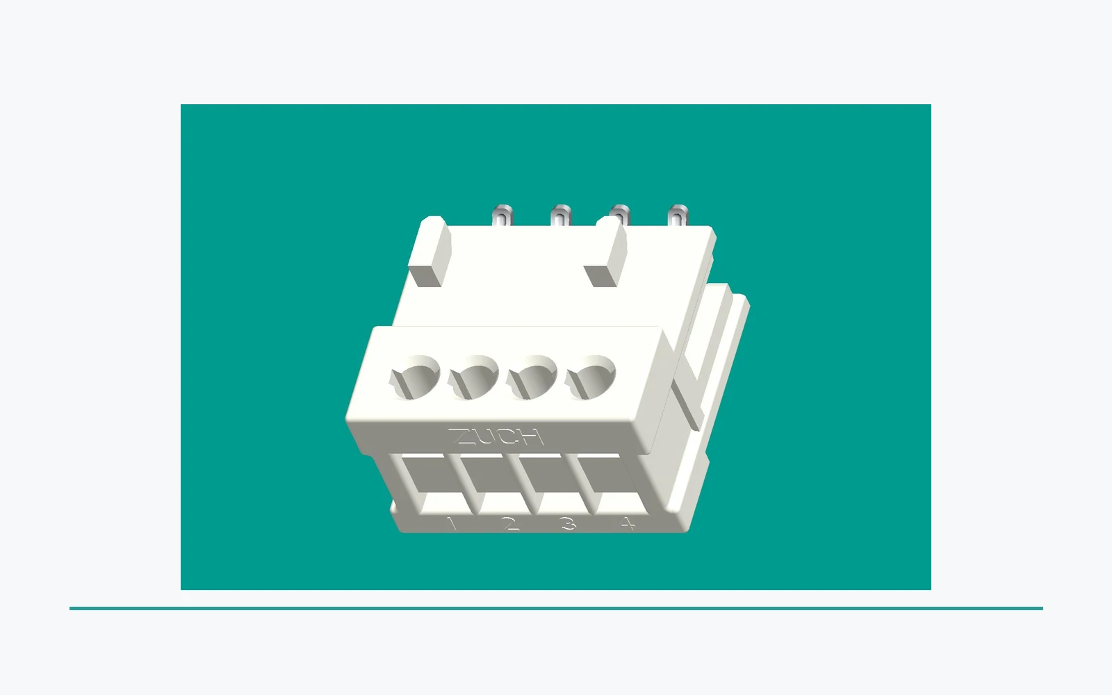
PCB connector removal is a reliability task, not simply disassembly. A wire-to-board plug is intended to mate and unmate; a through-hole or surface-mount (SMD) header is retained by solder joints. Confusing the two can turn a local replacement into conductor damage, inspection time, and scrap.
Why must unplugging and desoldering be treated as different operations?
How should a wire-to-board connector be released at its mating interface?
For a removable harness connector, work only after the equipment is de-energized under the approved low-voltage procedure. Record orientation, keying, wire colors, and latch position; support the board and depress the intended release feature. Pull the housing along the mating axis, never the wires or board-mounted header.
A pcb connector removal tool can be appropriate when it supports the housing or reaches a defined release feature without levering against solder joints. For compact appliance interfaces, engineers may compare the mating geometry with a documented RAST connector arrangement before planning service access. If the latch does not move with modest, controlled pressure, pause and inspect for a secondary lock, adhesive, or fastener rather than escalating force.
Why do board-mounted connectors require a controlled rework route?
To remove soldered pcb connectors, identify through-hole, SMD, or mixed construction first. Through-hole pins require cleared barrels; SMD leads require even thermal control and protection for adjacent parts. IPC rework guidance emphasizes inspection, controlled heating, cleaning, and acceptance—not speed.
Do not begin either operation on energized or mains-connected equipment. Use suitable ESD controls and magnification; lifted lands, laminate distress, corrosion, or unknown prior rework require specialist assessment.
What sequence safely unplugs a low-voltage wire-to-board connector?
- Disconnect the approved low-voltage supply, follow ESD procedure, and photograph the connector before release.
- Locate the primary latch and intended pull surfaces. Confirm it is a mating plug, not a soldered header.
- Support the board, actuate the latch with a non-marring aid if needed, and withdraw the housing in line with the axis. Do not pull conductors.
- Inspect latch, terminals, and pins for deformation or contamination before reuse.
This sequence is how teams remove pcb connectors without damaging pins when the connector was designed to unplug. The useful metric is not removal time alone; it is whether the interface can be re-mated, inspected, and function-tested without unplanned replacement. IEC 60512 provides methods used to evaluate connector characteristics, including mechanical and electrical behavior, but the product’s own specification still governs the permitted mating and service conditions. A power connector also needs its specified electrical conditions confirmed before it returns to service.
How should through-hole and SMD connectors be desoldered?
Trained personnel should desolder using an approved rework process, suitable fume extraction, and equipment appropriate to the solder alloy and board. Preserve pads, plated-through holes, traces, and nearby components; do not lift until every soldered retention point is released.
Which steps protect plated through-holes and pads?
- Document pin count, orientation, stakes, and underside joints; compare the footprint with the relevant PCB header geometry where helpful.
- Clear solder from each lead and verify each barrel is free before vertical movement. A manual pcb connector removal tool must not pry against a copper land.
- Release evenly, inspect every pad and hole under magnification, then clean and assess. If a lead remains fixed, re-evaluate rather than twist.
Which controls reduce pad lift during SMD connector removal?
- Shield adjacent sensitive parts and review land pattern, thermal mass, and anchor tabs. Broad thermal masses need a validated profile.
- Apply the approved localized profile until joints release together, then lift vertically; never slide across softened pads.
- Inspect for bridges, pad lifting, mask damage, and trace disturbance. IPC-7711/7721 is relevant rework guidance; compromised pads, vias, or conductors need specialist review.
Thermal exposure and pad condition are the two primary acceptance checks. Illustratively, forcing a stubborn 12-pin header can save minutes but create hours of trace repair, inspection, and repeat testing; controlled rework is usually lower total cost.
How should tools and controls be matched to removal risk?
| Removal situation | Suitable control | Main risk addressed | Maintenance and TCO implication |
|---|---|---|---|
| Latched wire-to-board plug | ESD-safe support and release aid | Broken latch, bent pins, wire pull-out | Preserves the mating interface |
| Through-hole header | Desoldering station, magnification, support | Lifted pads and blocked holes | Avoids board replacement |
| SMD connector with anchor tabs | Validated profile, shielding, controlled lift | Pad movement and heat damage | Higher setup; lower returns risk |
| Corroded or prior-reworked footprint | Specialist assessment | Hidden conductor damage | Prevents repeated failures |
Tool choice should follow the assembly, not convenience. A third use of a pcb connector removal tool is justified only when its contact surfaces and action match the documentation. A pointed pick used as a lever adds uncontrolled point loading and can create later intermittent faults. The removal plan should preserve the same geometry and access required for power-connector installation.
How does the application determine the acceptable removal process?
| Application decision | Preferred route | Evidence to retain | Escalation trigger |
|---|---|---|---|
| Field replacement of a removable harness | Unplug, inspect, and re-mate to approved work instructions | Photos, connector orientation, functional test result | Latch damage or pin deformation |
| Low-volume repair of a through-hole board | Controlled desoldering and pad inspection | Rework record, footprint inspection, continuity check | Incomplete solder release or lifted land |
| Dense SMD control board | Qualified rework process with thermal and ESD controls | Profile record where required, optical inspection, test result | Adjacent-part movement or laminate distress |
| OEM change or recurring service issue | Review connector selection, access, and documented service process | Failure analysis, drawing revision, validation plan | Repeat returns or uncertain connector identification |
Procurement teams should request drawings, mating information, approved rework limits, and traceable inspection criteria before awarding a replacement or service program. A broad portfolio of connector interfaces can make selection easier, but dimensional fit alone is not sufficient; intended use, current path, retention, service access, and validation evidence must align.
Which standards and workmanship records support a defensible rework decision?
- IEC 61984 addresses safety requirements and tests for connectors within its defined scope; applicability depends on the connector’s intended use and relevant product conditions. It should not be cited as a blanket approval for an entire end product or a field-rework procedure.
- IEC 60512 is a series of test methods for electromechanical components, including connectors. It supports defined testing and comparison; it is not a standalone product certification and does not substitute for a product specification.
- UL 1977 concerns component connectors for use in data, signal, control, and power applications. Where component recognition is relevant, buyers should verify the actual component file, conditions of acceptability, and end-product requirements rather than infer recognition from a catalog description.
- IATF 16949 defines automotive quality-management-system requirements for applicable organizations; it is a quality-system scope, not a connector performance rating or product certification.
Unsupported standards claims can delay supplier qualification, confuse destination-market obligations, and leave repair teams without defensible acceptance criteria. The specification, destination market, intended use, end-product standard, and any marketing claim should be reviewed together. When a claim is material to a purchase decision, request the applicable document and confirm its exact scope.
How can removal readiness be designed into connector selection?
- Specify whether the service action is unplugging, terminal extraction, or board-level rework; these are different operations with different tooling and training needs.
- Require drawings that show keying, latch access, pin numbering, mounting features, and the board footprint before the design is released.
- Define inspection criteria for pins, latches, solder joints, pads, and functional continuity so a technician can make a consistent disposition decision.
- Ask suppliers to distinguish product documentation from test-method references and quality-system statements. For automotive programs, supplier quality-system evidence should be reviewed in the context of the program’s approved sourcing requirements.
For teams sourcing rectangular connectors, RAST systems, terminals, or appliance and motor/compressor interfaces, ZUCH can be considered when documented fit, application requirements, and validation evidence align. Its stated IATF 16949:2016, CNAS-recognized laboratory, and UL Witness Lab qualifications should be evaluated against program and component documentation; they do not replace product-specific verification. Plan the service route early enough to protect pins and pads.
How can technicians choose the least damaging PCB connector removal route?
Choose the route by connector construction and board risk, not by the tool already on the bench. A wire-to-board plug with a designed latch should be released along its mating axis; a through-hole connector may require controlled solder removal from all pins; an SMD connector may require even heating and support to avoid pad lift. If the connector is bonded, shielded, mechanically staked or surrounded by heat-sensitive parts, the process should be reviewed before work starts.
- Identify the restraint. Photograph the orientation, latch, stakes, screws, solder joints and any adhesive before touching the board.
- Protect the assembly. Isolate power, apply ESD controls, shield nearby plastics and support the board so the connector is not used as a lever.
- Release evenly. Remove solder or disengage the latch across the complete interface; never force one corner while another restraint remains.
- Inspect before reuse. Check pads, plated holes, traces, pins, housing and alignment under magnification, then document continuity and the disposition decision.
If the board construction or previous repair is unknown, escalation is safer than adding heat or force. The objective is not merely to remove the connector; it is to preserve a verifiable board and interface for the next operation.
Which removal route matches the board risk?
The route should follow the connector construction and the board's repair value, not the tool already available.
| Review point | Record or question | Why it closes risk |
|---|---|---|
| Mated plug | Support the board and release the intended latch or lock | Prevents wire pull and housing damage |
| Through-hole body | Identify solder and mechanical restraints before controlled heat | Reduces plated-hole and pad damage |
| SMD body | Support the connector and control heat across the joint set | Reduces pad lift and laminate stress |
| Unknown or damaged board | Stop, document and escalate to qualified rework | Prevents repeated damage from force or heat |
FAQ: How can PCB connector removal avoid hidden board damage?
Can a PCB connector be removed by pulling the wires?
No. Pulling wires can disturb crimp retention, break conductors, or overload the board-mounted header. Release the designed latch and pull the housing along the mating axis; if the connector is soldered to the PCB, use a qualified rework route instead.
What is the safest way to remove soldered PCB connectors?
The safest approach is a documented, ESD-controlled rework process that matches the connector’s through-hole or SMD construction. To remove soldered pcb connectors reliably, release all soldered and mechanical retention points before lifting, then inspect pads and traces under magnification.
How do technicians remove PCB connectors without damaging pins?
They identify the mating interface, support the assembly, operate the intended latch, and pull only on the housing. To remove pcb connectors without damaging pins, never use the wires as a handle and stop if the connector does not release as its design suggests.
When should a board go to a rework specialist?
Escalate when a pad begins to lift, solder does not release evenly, laminate discoloration appears, or the footprint has unknown previous repair. A specialist can determine whether repair is technically and commercially justified before further damage is introduced.
Does a connector standard prove that a repaired board is compliant?
No. A connector standard or test-method reference has a defined scope, while repaired-board acceptance also depends on the intended use, customer requirements, workmanship criteria, and applicable end-product obligations. Retain the rework record and verification evidence required by the program.
How do you remove a connector from a circuit board without lifting pads?
First identify every mechanical and soldered restraint, then use the lowest-risk controlled heat and extraction method that matches the board construction. Keep the connector supported, avoid levering against the laminate, remove solder evenly, and inspect pads and plated holes under magnification before deciding whether the board is fit for reuse. If solder will not release or a pad begins to move, stop and escalate to qualified rework personnel.
Can a PCB connector be removed without pulling on the wires?
Yes. Release the designed latch or restraint, support the assembly, and keep extraction force on the connector or tool rather than on the conductor or crimp.
Why must unplugging and desoldering be separated?
They use different restraints and create different damage modes. A method suitable for a removable plug is not automatically suitable for a soldered header.
When should a board be escalated instead of heated again?
Escalate when pads lift, solder will not release evenly, the connector identity is uncertain, laminate damage appears or hidden restraints are suspected.
Does IPC-7711/21 automatically approve a rework method?
No. The revision table identifies controlled IPC documents; the actual rework procedure, board class and acceptance criteria still need to be selected for the assembly.
How can technicians reduce pad-lift risk?
Identify all restraints, support the board, control heat and force, and stop when the joint or laminate response is abnormal instead of compensating with more force.
What evidence should a repaired board retain?
Record the connector identity, restraint, tool/process, inspection result, damage found, replacement part and the responsible disposition decision.
References
- IEC 60512-1:2018 — Connectors: tests and measurements — public scope checked 2026-10-14; it does not establish a product-specific rating, certification or application approval.
- IEC 60664-1 consolidated publication — Insulation coordination — public scope checked 2026-10-14; it does not establish a product-specific rating, certification or application approval.
- Global Electronics Association IPC standards revision table — public scope checked 2026-10-14; it does not establish a product-specific rating, certification or application approval.
- IEC 61984: Connectors — Safety requirements and tests — public scope checked 2026-10-14; it does not establish a product-specific rating, certification or application approval.
Conclusion
The least damaging PCB connector removal method is chosen before the connector is touched. First separate a removable mating operation from board-level desoldering, then identify latches, stakes, screws, solder joints and hidden restraints. Support the board, control heat and force, and record the point at which work must stop. A successful unplug does not validate a soldered rework method, and an IPC document listing does not by itself approve a particular board or process. Use the exact assembly instructions and acceptance criteria for the program. ZUCH's connector and PCB-interface categories can support a replacement or design review, while repair disposition remains with the responsible electronics manufacturer or rework organization.