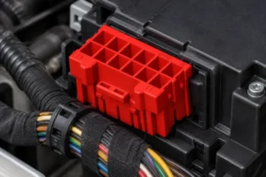
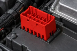
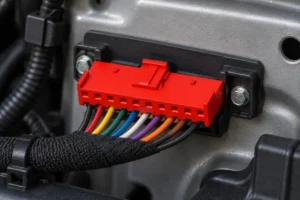
Zhejiang ZUCH Technology Co., Ltd.
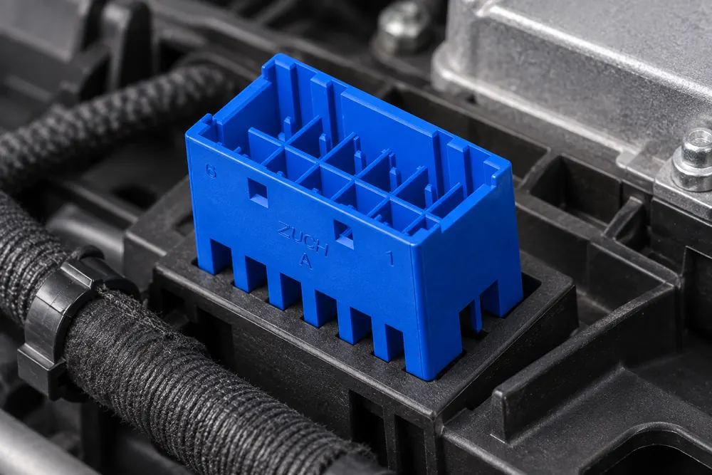
When a harness validation engineer in Stuttgart connected a replacement 14-way plug to a body controller, warning lamps appeared within seconds; the shell fitted, but the failure came from a different terminal map, an unmatched mating half, and unverified continuity—not a defective controller.
Summary: Choose a 14 pin automotive connector by more than cavity count. Confirm the connector family, male/female mating interface, keying, latch, terminal series, wire range, sealing, and the function assigned to each of the 14 positions. Before energizing the vehicle, verify all populated circuits cavity by cavity and test continuity plus isolation. SAE USCAR-2 and IEC 61984 can inform performance and safety evaluation, but they are standards—not automatic approval for a specific part or repair.
A 14-circuit connector groups multiple signals, power feeds, grounds, or communication lines into one serviceable interface. Vehicle makers may use this format at body-control modules, lighting assemblies, door harness branches, seat systems, instrument panels, or engine-bay sub-harnesses. Yet “14-pin” describes only the position count. Two products with 14 cavities can differ in pitch, keying, contact gender, terminal size, current capability, material, seal system, and mating geometry.
That distinction matters because a housing can appear to mate while contacts are misaligned or circuits are assigned differently. The result may be an open circuit, a short to an adjacent position, diagnostic trouble codes, or damage after power-up. A disciplined selection process begins with vehicle documentation and ends with an electrically verified assembly.
What does the 14-circuit application need the connector to carry?
First identify what the connector does in the vehicle. A dry-cabin branch carrying switch signals has different environmental needs from an under-hood interface exposed to moisture, temperature cycling, fluids, and vibration. Record vehicle make, model, year, trim, harness location, module designation, and connector reference from the OEM wiring diagram or service information.
What should a 14-position cavity map show?
Map positions 1 through 14 from both the mating face and wire side, because the views are mirrored and are easy to confuse. For every populated position, record circuit name, wire color, conductor cross-section, signal type, and terminal part number where known. Mark unused cavities and required cavity plugs. Photographs should supplement the drawing, not replace it.
Separate signal, power, ground, and data circuits in the review. Communication pairs may require controlled twist and shielding; power circuits require conductor and terminal sizing based on the approved design, not a guess from wire color. For service work, inspect OEM technical bulletins and the NHTSA vehicle-safety resources for relevant recalls or safety information before changing a safety-related harness.
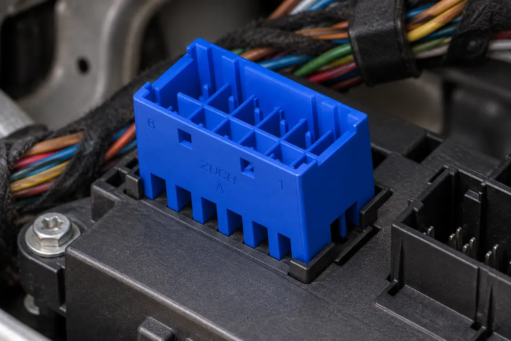
Why the housing, mating half, terminals, and seals must be specified together
A compatible housing must share the same connector family and mechanical interface. Compare part markings, overall dimensions, cavity pitch, polarization ribs, latch position, connector-position-assurance device, terminal-position-assurance lock, and mating-face profile. The correct male and female housings should engage fully without trimming keys, forcing the latch, or modifying plastic.
Why housing and terminal gender labels are not enough
“Male” and “female” can describe either the terminal or the housing, so use part drawings rather than informal labels. A receptacle housing may carry male blade contacts, while a plug housing may carry female receptacles. Procurement records should therefore identify the complete mating pair and its contacts, seals, secondary locks, and accessories.
Terminal selection is equally specific. Confirm contact interface, plating, conductor crimp range, insulation diameter, seal compatibility, and the applicator or service tool. Do not assume one terminal covers every wire in a 14-way shell; mixed signal and power positions may use more than one approved wire range or contact size. Our overview of automotive connectors and terminals explains how these elements work as a system.
Keying, coding, and polarization reduce mis-mating only when the buyer confirms the exact mating pair. They cannot protect against a wrong cavity map, a visually similar connector from another family, or a terminal that is inserted into an unsupported cavity. For that reason, the approval record should include both faces of the connector, the terminal table, and the secondary-lock position.
| Selection dimension | What must match | Failure if overlooked |
|---|---|---|
| Housing interface | Family, pitch, keying, latch, and mating-face geometry | Partial engagement or contact misalignment |
| Mating half | Complementary housing and terminal gender | No mating, damaged beams, or false latch |
| Terminal system | Contact series, wire range, plating, and crimp tooling | High resistance, weak retention, or early wear |
| Sealing package | Wire seal, interface seal, cavity plugs, and backshell | Moisture entry or seal displacement |
| Locking features | Primary lance, secondary lock, and CPA where specified | Terminal back-out under vibration |
When should a 14-pin connector be sealed instead of unsealed?
Use a sealed connector where the installed location may encounter water spray, condensation, road contaminants, engine fluids, or pressure changes. The sealing decision should come from the OEM environment and validation plan, not from a generic “waterproof” label. Cabin locations can still need sealing when they sit near doors, floors, HVAC drains, or convertible-roof mechanisms.
A sealed assembly works only when every element is compatible. The interface seal must seat correctly; each wire seal must match insulation diameter; unused cavities need the specified plugs; and the rear cover must not distort the wires. Wire seals that are too tight can tear during insertion, while loose seals can leak even when the housings are fully latched.
| Application location | Likely design emphasis | Verification priority |
|---|---|---|
| Instrument panel or dry cabin | Keying, packaging, service access, low insertion force | Cavity map, latch engagement, continuity |
| Door, seat, or floor branch | Flexing, abrasion control, possible moisture exposure | Strain relief, routing, seal condition |
| Engine bay | Heat, fluids, vibration, environmental sealing | Terminal retention and environmental test evidence |
| Lighting assembly | Condensation control, compact packaging, serviceability | Interface seal, cavity plugs, polarity |
| Module or controller interface | Position accuracy, signal integrity, CPA/secondary lock | 100% circuit and terminal-position verification |
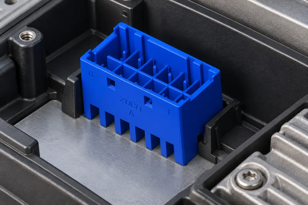
How to verify terminal position, repair quality, and continuity before power-up
Before inserting contacts, orient the housing to the approved cavity view and check every wire against the 14-position map. Insert each terminal until its primary lance captures, then apply the service-manual retention check. The secondary lock should close flush with normal hand pressure; if it does not, locate the high or misoriented terminal instead of forcing the lock.
When is a single-circuit repair safer than replacing the full harness?
A single terminal can often be replaced when the housing cavity, lock, and mating contact remain undamaged and the OEM repair procedure permits it. Use the specified extraction tool, a new compatible terminal, and the validated crimp tooling. Replace the complete housing or pigtail if there is heat deformation, broken keying, a cracked lock, corrosion extending into multiple cavities, or loss of terminal retention. See the practical process in our guide to automotive electrical connector repair.
After assembly, perform a de-energized point-to-point continuity test for all populated positions and check isolation from adjacent circuits. Compare measured resistance with OEM limits or an approved baseline; do not use a test voltage that can harm connected electronics. Then mate the connector, scan for diagnostic codes where appropriate, and complete a functional test under the original operating conditions.
The hidden cost of a wrong connector is rarely the housing price. It includes pin-map research, repeated disassembly, damaged terminals, vehicle downtime, diagnosis of intermittent faults, and possible warranty returns. As an illustrative TCO comparison, even one extra service visit may cost more in technician time and lost vehicle availability than a documented mating set and controlled terminal kit; use your actual labor and downtime rates rather than a fabricated universal figure.
Which standards and procurement controls reduce approval risk?
SAE USCAR-2 describes performance requirements and test procedures for automotive electrical connector systems. IEC 61984 addresses safety requirements and tests for connectors within its stated scope. These documents are test and design references; citing them does not mean a particular connector, harness repair, or supplier is automatically certified.
Applicability depends on destination market, vehicle system, voltage, installation environment, OEM requirements, and the supplier’s claimed scope. Unsupported claims such as “USCAR approved” or “IEC certified” can create audit, sourcing, warranty, and misrepresentation risk. Buyers should request the exact drawing revision, material declaration, test report, sample identity, and conditions behind any claim, then validate the assembly in the intended harness.
For selection and purchasing, use four controls:
- Freeze the mating-pair part numbers, cavity map, terminal options, seals, locks, and accessories in the specification.
- Approve crimp tools and measurable acceptance criteria for every wire and terminal combination.
- Inspect first articles for dimensions, keying, terminal position, retention, continuity, and mating operation.
- Maintain revision, lot, and inspection traceability so field issues can be isolated without replacing unrelated parts.
ZUCH can support buyers comparing a 14 pin automotive connector, its mating housing, and compatible terminal options. The responsible approach is to share the application, cavity map, wire sizes, sealing needs, and validation requirements, then evaluate drawings and samples before production approval. For broader context, consult this guide to automotive electrical connectors.
Frequently asked questions
What is a 14-pin automotive connector typically used for in vehicle control and harness branches?
It can consolidate control signals, power, grounds, lighting circuits, or data lines at body modules, doors, seats, instrument panels, lamps, and sub-harness junctions. The 14 positions do not define one universal application; the vehicle wiring diagram and connector family determine the actual function.
How do I confirm that a 14-pin automotive connector matches my vehicle wiring?
Match the vehicle and harness reference, housing part number, keying, latch, mating face, and all 14 cavity assignments. Also verify terminal series, wire range, seals, and secondary locks. Complete continuity and isolation checks before applying power.
Do 14-pin automotive connectors need a matching male and female housing?
Yes, the connector must use the intended complementary housing and contact system. Do not rely only on “male” or “female” wording, because housing and terminal gender can be described differently; confirm the mating-pair drawings and part numbers.
What terminal and wire-gauge options are common for a 14-pin automotive connector?
Options vary by connector family and may include different contact sizes or crimp ranges for signal and power circuits. There is no reliable universal gauge list for every 14-way housing. Use the manufacturer’s terminal drawing and the OEM circuit specification for each cavity.
When should I choose a sealed 14-pin automotive connector?
Choose sealed construction when the installed location can face moisture, condensation, fluids, contaminants, or significant environmental cycling. Confirm that the housing seal, individual wire seals, cavity plugs, and insulation diameters form one compatible sealing system.
Can I replace one terminal in a 14-pin connector without replacing the full housing?
Often yes, if the cavity, locking features, seals, and mating contact are undamaged and the OEM procedure allows a terminal repair. Use a new specified contact and validated crimp tool, then test retention, continuity, and isolation. Replace the housing or pigtail when damage affects fit, locking, or multiple circuits.
Sources for 14-pin connector fitment and repair decisions
- SAE International, USCAR-2, Performance Specification for Automotive Electrical Connector Systems
- International Electrotechnical Commission, IEC 61984, Connectors—Safety requirements and tests
- National Highway Traffic Safety Administration, vehicle safety and recall resources
- OEM wiring diagrams, service procedures, and connector drawings for the target vehicle
The soundest connector choice is the one that mates correctly, places every circuit correctly, and proves both facts through inspection and testing. To compare housings and terminals for your application, review ZUCH connector products and contact the team with your mating interface, 14-position map, wire specifications, and environment.