Zhejiang ZUCH Technology Co., Ltd.
When an automotive service technician in Los Angeles encountered an intermittent fuel-pump fault, he watched a short depinning clip, selected the thinnest metal pick in his drawer, and pushed until the terminal moved. The circuit worked for one road test, then failed again: the retention tang had folded, the cavity seal was cut, and the loose terminal opened whenever the harness flexed. The connector was not worn out. The technician had treated three separate mechanisms – secondary lock, primary lance, and wire seal – as one obstruction.
Summary: Safe automotive electrical connector disassembly follows a zero-force sequence: identify the connector, isolate the circuit, release the secondary lock, match the release blade to the primary retention feature, unload the terminal, withdraw it by the wire and insulation support, inspect it, then verify retention and electrical performance. The correct automotive terminal removal tool should depress a latch without widening the cavity or touching the contact interface. A car wiring harness terminal tool set is useful only when technicians can map each profile to a documented connector family. SAE connector-performance practices and ASE electrical-service training reinforce the same principle: control the interface before applying force.
Why Does an Automotive Terminal Removal Tool Need to Match the Locking Architecture?
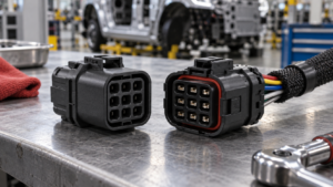
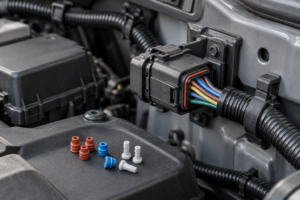
Most serviceable automotive terminals are held by more than friction. A primary lance locks the metal terminal into the cavity; a secondary device – often called a TPA, CPA, wedge, retainer, or terminal-position assurance feature – prevents unintended release or incomplete seating. Sealed connectors add individual wire seals or a mat seal.
Tool geometry follows that architecture. A flat blade may depress a top lance, twin blades may release opposed locking ears, a round tube may collapse radial fingers, and a forked profile may straddle a contact while reaching a hidden shoulder. Similar-looking cavities can require different insertion depths.
The first safety rule is therefore diagnostic: no tool enters until the technician can point to the secondary lock, identify the primary retention direction, and state whether access is from the mating face or wire side. If any answer is uncertain, the connector drawing or OEM repair information takes priority over trial and error.
We recommend photographing the connector from both sides before work begins. A 20-second image records lock position, wire colour, cavity numbering, seal orientation, and routing; that evidence is more reliable than memory during reassembly.

How Should a Technician Prepare for Automotive Electrical Connector Disassembly?
Preparation starts with circuit classification. A 12 V circuit can still deliver enough current to overheat a bridged tool or damaged wire; restraint systems, pyrotechnic devices, high-voltage vehicles, and safety-critical controls require the OEM isolation procedure and trained personnel. Voltage level alone does not define risk. For related selection references, see How to Depin Automotive Connector? and How to Disconnect Automotive Electrical Connectors?.
Before automotive electrical connector disassembly, the technician should save required memory settings, switch the ignition off, remove the key or disable keyless wake-up, isolate the specified power source, observe the OEM waiting time, and verify the circuit state with an appropriate instrument where the procedure requires it.
- Clean first: compressed debris can jam a lock; aggressive solvent can swell seals or remove cavity markings.
- Stabilize the connector: support the housing on the bench or by hand so insertion force does not bend the harness branch.
- Mark the cavity: record connector ID, cavity number, wire colour, stripe, gauge, and terminal orientation before extraction.
- Set magnification and light: a 3x to 10x inspection aid often prevents a blind, oversized-tool attempt.
Gloves and eye protection should match the workshop procedure, but dexterity matters. If a glove prevents the technician from feeling the terminal unload, the task needs a different glove or fixture – not more pulling force.
How Does a Car Wiring Harness Terminal Tool Match the Terminal Profile?
Selection should begin with a connector or terminal reference, not vehicle make alone. One vehicle platform can contain dozens of connector systems from different suppliers; one housing family can use several terminal sizes. Year, model, and circuit location narrow the search but do not prove tool fit.
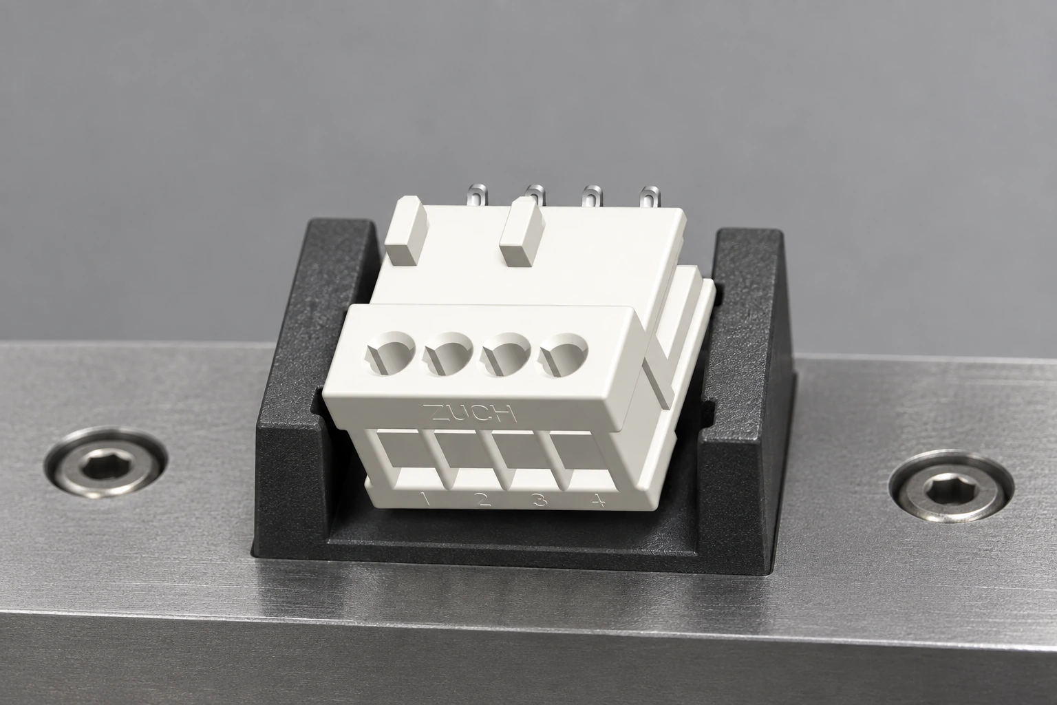
A car wiring harness terminal tool is correctly matched when its working end reaches the retention feature with clearance from the cavity walls and contact beams. It should not scrape plating, enter the female contact box, or spread a stamped spring feature.
| Retention form | Likely tool profile | Correct-fit signal | Wrong-fit warning |
|---|---|---|---|
| Single top lance | Thin flat blade with controlled width and stop | Lance releases with a short axial movement | Blade wedges between terminal and cavity wall |
| Opposed locking ears | Twin blade or correctly sized sleeve | Both ears unload together | One ear releases while the other deforms |
| Radial fingers | Round tube matched to terminal diameter | Tube slides concentrically around the pin | Tube binds or polishes the contact surface |
| Housing-integrated latch | Fork, hook, or OEM-specific profile | Housing latch moves without whitening plastic | Cavity lip bends or stress-whitens |
Tool thickness, width, corner radius, surface finish, and insertion length all matter. A profile that is 0.2 mm too thick can preload a cavity wall before it touches the latch; a polished edge can be safer than a stamped burr even when both share the same nominal dimension.
Before approving a car wiring harness terminal tool, a workshop should trial it on an identified spare connector and record the access side, insertion depth, and release sensation; the same controlled trial also confirms whether the chosen automotive terminal removal tool clears the contact interface throughout its travel.
What Is the Zero-Force Process for Automotive Electrical Connector Disassembly?
“Zero force” does not mean no physical force; it means the technician never uses extraction force to overcome an unidentified lock. Wire tension is kept near zero while the release feature is engaged, and withdrawal begins only after the terminal can move in its designed axis.
- 1. Map: confirm connector identity, cavity, terminal orientation, access face, and lock sequence.
- 2. Isolate: follow the OEM electrical shutdown and waiting procedure; verify the safe state where required.
- 3. Clean and inspect: remove loose debris and look for previous pick marks, heat damage, water tracks, or backed-out terminals.
- 4. Unlock: move the secondary lock only to its service position; forcing full removal can break a captive retainer.
- 5. Unload: push the wire gently toward the connector to remove tension from the primary lance.
- 6. Release: insert the matched automotive terminal removal tool parallel to the terminal until the retention feature disengages.
- 7. Extract: withdraw by the insulated wire immediately behind the seal or insulation support; never pull from a long unsupported span.
- 8. Prove: inspect, repair or replace, reinsert in the original orientation, close the secondary lock, perform a retention check, and verify circuit operation.
Stop if the wire stretches, the tool bows, plastic turns white, the seal bunches, or the terminal requires rising pull force. These are not signs that more force is needed; they show that a lock remains engaged or the tool path is wrong.
This evidence-gated method makes automotive electrical connector disassembly repeatable across a workshop because every hand movement has a visible condition for proceeding and a visible condition for stopping.

Which Damage Patterns Reveal Incorrect Tool Use?
Damage tells a sequence. A folded retention tang usually points to extraction before complete release; a scratched contact box points to insertion through the electrical interface; a torn seal points to off-axis withdrawal or a burr; stress whitening points to an oversized tool or an unreleased secondary lock.
| Observed symptom | Likely mechanism | Required action | Reuse decision |
|---|---|---|---|
| Terminal backs out after insertion | Retention lance flattened or secondary lock not closed | Remove correctly; inspect terminal and cavity; replace damaged part | Do not rely on bending a fatigued lance back repeatedly |
| Intermittent high resistance | Contact beam spread, plated area scratched, or crimp disturbed | Inspect under magnification; perform specified electrical checks | Replace if contact geometry or plating is compromised |
| Water path in cavity | Seal cut, rolled, contaminated, missing, or wrong size | Replace seal or terminated lead; clean and dry per approved method | Do not reuse a visibly cut or permanently deformed seal |
| Housing cavity is enlarged | Tool used as a lever or blade too wide | Compare with an undamaged cavity; replace housing if retention is uncertain | Housing repair with adhesive is not a retention validation |
During automotive electrical connector disassembly, the honest answer is that a damaged terminal is often cheaper than an uncertain terminal. Replacement is preferred when the contact beam, plating, crimp, retention feature, or seal cannot be verified against the repair specification.
Which Standards Support Safe Automotive Electrical Connector Disassembly?
No single general standard replaces the connector maker’s service instruction. SAE connector standards and recommended practices establish performance context for vibration, sealing, electrical continuity, environment, and mechanical integrity; the exact document depends on connector class and application.
ASE electrical and electronic systems training provides a professional competence framework for diagnosis and repair. High-voltage and electrified-vehicle work requires additional training, authorization, personal protective equipment, isolation, and verification procedures; a depinning tool does not make an unqualified task safe.
ISO 9001 supports controlled design, manufacturing, inspection, and corrective action for the tool supplier. IATF 16949 is relevant when the quality system supports automotive production supply; it does not certify that every tool fits every connector. CE and RoHS evidence should be checked against the actual product, market, and applicable legal scope.
A workshop using a car wiring harness terminal tool should retain OEM repair information, tool identification, technician authorization, and inspection criteria. The commercial consequence of weak control is not limited to a broken housing; it includes comeback labour, replacement harnesses, diagnostic time, and liability around safety-related circuits.
How Should a Workshop Select and Maintain an Automotive Terminal Removal Tool Set?
- Buy each automotive terminal removal tool by supported connector families and dimensional drawings, not by piece count. A 60-piece unlabeled set can provide less coverage than 12 documented profiles.
- Require permanent profile identification, a placement map, protective storage, corrosion control, and replacement availability for worn blades.
- Inspect working ends under magnification. Retire tools with burrs, rolled edges, cracks, permanent bends, corrosion pits, or altered tips.
- Separate release tools from test probes and general picks. Visual similarity should not permit substitution across functions.
- Train on sacrificial connectors before customer work and keep known-good terminals and housings for fit verification.
ZuchTech provides terminal-removal sets, connector service tools, harness depinning tools, crimping tools, and electrical repair kits supported by ISO 9001, CE, RoHS, and IATF 16949 quality-system credentials where applicable. Distributors and workshop buyers can review the [Internal link] ZuchTech automotive electrical tool range when building a documented connector-family coverage plan.
A buyer specifying a car wiring harness terminal tool kit should send target terminal families, vehicle markets, tool drawings or samples, expected annual volume, packaging, language, and traceability requirements through the [Internal link] ZuchTech project channel.
What Should the Repair Record Prove Before the Vehicle Is Released?
The repair record should identify the vehicle, connector, cavity, original symptom, terminal and seal part numbers, release tool ID, observed damage, repair method, crimp equipment where used, retention check, electrical verification, and final scan or functional result.
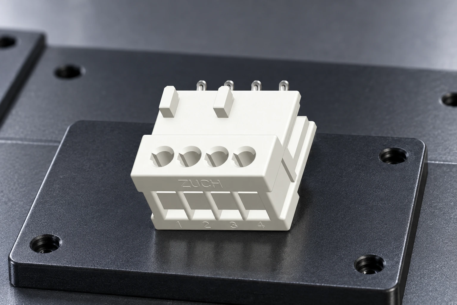
A light pull confirms that the terminal is retained, but it is not a substitute for the specified terminal pull test or contact-resistance method. The technician should use the OEM or connector repair criteria and avoid inventing a force value on the workshop floor.
Tool inspection can be linked to the same record. A frequently used automotive terminal removal tool should have a simple condition log so a bent profile is removed before it damages several customer connectors.
The record should also identify the car wiring harness terminal tool profile used; if a repaired circuit returns, that detail allows the workshop to separate a tool-fit problem from a terminal, crimp, seal, or diagnosis problem.
Which References Support This Connector-Service Method?
- [External source] SAE International Standards – automotive connector, electrical-system, and mobility engineering standards.
- [External source] National Institute for Automotive Service Excellence – technician certification and automotive electrical-service competence context.
- [External source] National Highway Traffic Safety Administration – vehicle-safety information and electrified-vehicle safety context.
- [External source] International Organization for Standardization – ISO 9001 quality-management framework used in supplier qualification.
What Is the Final Safety Judgment?
Safe automotive electrical connector disassembly is not defined by how quickly a terminal leaves the housing. It is defined by whether the lock was understood, the circuit was controlled, the contact and seal remained serviceable, and the repair was verified after reassembly.
The correct car wiring harness terminal tool does not overpower the connector; it removes one designed restraint while leaving every other function untouched.
ZuchTech builds terminal-removal, harness-service, connector, and electrical-repair tool solutions for that moment. Workshops and distributors can share their target connector families, tool profiles, kit structure, quantity, packaging, certification, and destination through the [Internal link] ZuchTech official website to request a matched proposal.