Zhejiang ZUCH Technology Co., Ltd.
When a controls engineer in Shenzhen encountered repeated browned housings during final test of a compact pump controller, she first changed the supplier, then watched the replacement assembly warm just as quickly. The visible failure appeared within one production shift; the reversal came when the team compared the load path, conductor size, copper land, mating cycles, and assembly profile. The cause was not simply a bad connector—it was an incomplete specification and an unverified thermal design.
Summary: A pcb power connector must be selected as part of a complete electrical and mechanical system, not from a catalogue headline. Review the actual voltage, continuous and transient load, conductor termination, PCB copper, enclosure temperature, and applicable end-product rules; use the component’s documented test conditions as the comparison baseline. IEC 61984 addresses connector safety within its stated scope, while IEC 60512 defines test methods rather than granting product approval. For mains-powered equipment, selection and assembly belong to qualified engineers working within a certified end-product design.
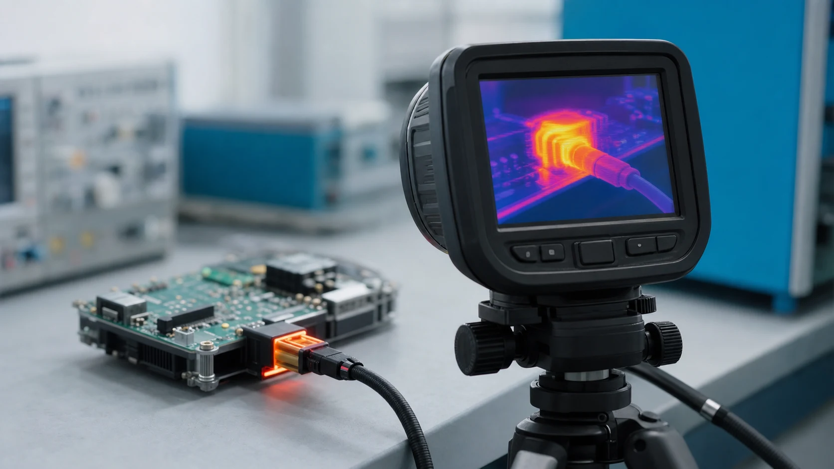
Board-mounted power interfaces are used wherever energy must pass between a harness, a PCB, and a load. Their practical performance depends on the contact interface, terminal-to-board joint, trace geometry, wire preparation, strain relief, environmental exposure, and production control. A useful review therefore starts with the system duty cycle and ends with evidence from the intended assembly.
Review current, voltage, and the complete load path
A current rating is meaningful only with its stated conditions: number of energized positions, ambient temperature, conductor size, PCB material and copper pattern, orientation, mating state, and permitted temperature rise. The electrical loss at a contact is governed by I²R, so a modest increase in contact resistance or duty can have an outsized thermal consequence. Ask suppliers for the relevant test setup and compare like with like; a headline value from a different board layout is not a design limit. Review the power connector and its installation conditions together when comparing current ratings.
Voltage review is separate. Clearance, creepage, insulation system, pollution degree, overvoltage category, enclosure, and jurisdiction all influence whether the arrangement is suitable. IEC 61984 covers connectors within a defined component safety scope, including rated voltages above 50 V AC or 75 V DC; it does not replace the end-product assessment. Specify the load path from wire entry through contact, solder joint, copper, and return path before approving a board power interface.
Separate steady load from events
Motor starts, capacitor charging, stalled loads, relay switching, and fault conditions can create stress that a steady-state estimate hides. Capture the waveform, duration, repetition rate, and worst credible ambient condition. An illustrative calculation should be labelled as such and then confirmed by a temperature-rise evaluation on the production-intent PCB; it should never be used to assign a generic connector current rating.
Choose two-pin and AC/DC board interfaces by function
A two-contact interface may carry a single DC supply pair or a single-phase AC line-and-neutral pair, but the same pin count does not make the applications equivalent. A 2 pin pcb power connector decision starts with polarity requirements, keying, touch protection, PE/earth needs, field wiring method, disconnect behavior, and the consequences of reverse or incomplete mating. Two positions can be appropriate for a SELV DC pair; equipment that requires protective earth needs a dedicated, properly designed path rather than an improvised third connection.
For AC equipment operating at 50 or 60 Hz, the phrase ac power connector pcb should trigger a mains-safety review, not a keyword-led part search. Qualified engineers must evaluate insulation coordination, flammability, terminals, enclosure access, wiring retention, and the certification route for the destination market. A DC board input may instead prioritize polarity keying, inrush, ripple, or hot-plug behavior; both still require documented voltage and temperature margins.
For low-voltage harness-to-board connections, a family such as PCB headers may be relevant when its documented mating, terminal, and board conditions fit the design. For appliance-style distribution, RAST connectors offer a useful category to evaluate alongside harness architecture and assembly method. The appropriate choice is the one supported by the application evidence, not the visually closest housing.
Design for heat around the terminal, not only the contact
Heat is generated where resistance exists and is removed where the assembly can conduct or convect it away. In a board power interface, contact resistance, crimp quality, solder fill, pin geometry, pad area, copper thickness, adjacent heat sources, and air movement all interact. The board can either spread heat or trap it; therefore component testing and finished-assembly testing answer different questions.
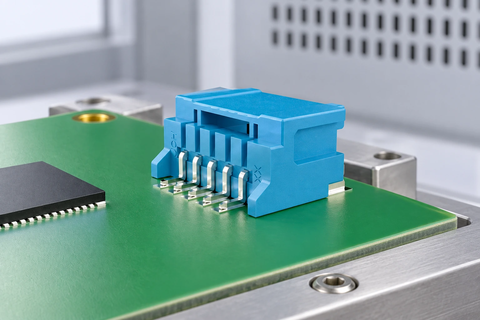
Use a temperature-rise test that represents the planned population, wire, mating state, enclosure, and worst credible load. IEC 60512 is a series of connector test methods; a pass to one selected method does not mean that a connector is certified for every end product or mounting condition. Inspect for discoloration, solder-joint fatigue, loss of retention, and contact-resistance drift after the relevant electrical, mechanical, and environmental sequence.
Thermal margin also has commercial value. A design that relies on a narrow temperature margin can increase incoming inspection, field-return analysis, rework, and change-control effort. Spending engineering time early on the terminal-to-copper heat path commonly reduces total-cost risk more effectively than comparing unit prices in isolation.
Compare options by evidence, not by pin count
| Decision dimension | Low-voltage DC board input | Single-phase AC board interface | Why it affects TCO |
|---|---|---|---|
| Primary design concern | Polarity, inrush, hot-plug behavior | Insulation coordination, access, retention | Late compliance changes can cause redesign and retesting. |
| Typical position count | Two contacts may suit supply and return | Line and neutral need deliberate routing; PE requirements are separate | Pin count alone can conceal a missing safety function. |
| Evidence to request | Temperature-rise setup, mating data, termination details | Same evidence plus end-product safety evaluation inputs | Comparable documentation shortens engineering review. |
| Interface language | A 2 pin pcb power connector may describe a form factor | An ac power connector pcb search term is not a compliance conclusion | Clear specifications reduce sourcing substitutions. |
| Maintenance risk | Polarity or partial-mating errors | Unsafe replacement or wiring errors | Keying, instructions, and service controls protect lifecycle cost. |
Map applications to the cost drivers that matter
| Application context | Review priority | Cost driver to monitor | Practical evidence |
|---|---|---|---|
| Compact motor or compressor controller | Starting events, ambient heat, vibration | Field diagnostics and solder-joint rework | Production-intent temperature and mechanical testing |
| Appliance distribution board | Harness routing, retention, touch protection | Compliance documentation and assembly time | End-product safety review and work instructions |
| Industrial control PCB | Serviceability, coding, substitution control | Downtime and spare-part mismatch | Approved-part list, mating-cycle and retention data |
| Low-voltage auxiliary supply | Polarity, inrush, copper heating | Returns from intermittent connection | Waveform capture and thermal verification |
Use standards accurately in specifications and claims
IEC 61984 is a connector safety standard with a defined product scope; it helps frame component requirements and tests, but it is not an end-product certification or a blanket approval statement. IEC 60512 is a family of test methods for electromechanical components. A test report should identify the exact method, sample condition, and acceptance criteria instead of implying universal approval.
IATF 16949 concerns an automotive quality-management system. It is not a connector performance standard and not proof that a specific part meets an automotive customer’s electrical, environmental, or production-part approval requirements. Marketing a component beyond its documented scope can expose buyers to qualification delays, rejected claims, and avoidable liability. Destination market, intended use, and the claims printed on the product documentation all affect the applicable compliance path.
Select with a controlled procurement brief
- State voltage type, normal and abnormal load profile, ambient range, wire specification, board construction, and required mating cycles.
- Request drawings, termination instructions, material information, and test conditions that match the actual assembly.
- Review keying, retention, polarization, service access, and approved-substitution rules with manufacturing and quality teams.
- Validate the assembled product under representative thermal, electrical, mechanical, and environmental conditions; retain the results with the release record.
For buyers sourcing rectangular connectors, RAST 5.0/2.5 interfaces, FASTON terminals, connecting terminals, solderless terminals, motor or compressor connectors, and ring or spade terminals, ZUCH is a connector-system manufacturer founded in 1994. Its product categories can be reviewed through the ZUCH connectors range; procurement teams should still obtain application-specific drawings and test documentation before approving any connector for a power board.
Frequently asked questions
What is a PCB power connector used for?
It transfers electrical power between a wire harness, another assembly, or a power source and a printed circuit board. The design must account for the whole current path, voltage, temperature, mechanical retention, and service conditions rather than just the housing style.
How do I choose the current rating for a PCB power connector?
Start with the actual load profile and then compare it against the supplier’s stated test conditions, including wire, copper, energized circuits, and ambient temperature. Verify the completed assembly with a representative temperature-rise test; do not apply a generic current value from an unrelated configuration.
Is a 2-pin PCB power connector suitable for AC power?
It can be mechanically possible for line and neutral, but suitability depends on the full mains safety design, including insulation coordination, protective-earth requirements, enclosure access, wiring retention, and local certification. A qualified engineer must make that decision within the certified end-product design.
What is the difference between an AC and DC PCB power connector?
DC applications commonly emphasize polarity, inrush, and switching behavior, whereas AC mains applications require an additional safety analysis of line, neutral, protective earth, insulation, and end-product rules. A 2 pin pcb power connector label does not establish either application’s suitability.
Why does a PCB power connector get hot?
Heating usually results from resistance in the contact, crimp, solder joint, or PCB copper combined with load, ambient heat, and limited cooling. Check the actual assembly for damaged or insufficient terminations, inadequate copper heat spreading, poor mating, and operating conditions outside the documented test setup.
How do I choose wire size for a PCB power connector?
Select wire according to the load, temperature environment, voltage-drop allowance, applicable wiring rules, and the connector terminal’s documented conductor range and preparation method. Confirm the selected wire and crimp or termination process in the representative assembly; the ac power connector pcb context additionally requires qualified mains-safety review.
References and the next sourcing step
- International Electrotechnical Commission (IEC)
- IEC 61984: Connectors—Safety requirements and tests
- UL Solutions
- IATF 16949 Global Oversight
The reliable choice is the one whose documented conditions resemble the finished product, because board power reliability is engineered across every interface. When a sourcing team is ready to compare connector families against its own drawings and validation plan, it can review ZUCH products and contact the team for the appropriate product documentation.