Zhejiang ZUCH Technology Co., Ltd.
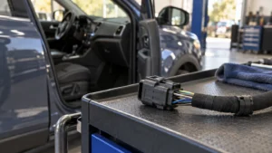
When a manufacturing engineer in Suzhou encountered repeated heat marks at the input of a compact appliance control module, the team replaced the plug assembly and watched the failure return during the next production run. The visible problem was a darkened terminal after a short current cycle; the reversal came when the review found an incomplete interface specification—contact material, wire preparation, crimp process and mating retention had been treated as separate purchasing details rather than one system.
Summary: A power connector is an interconnect system that transfers electrical energy through matched contacts, an insulating housing, a termination method and usually a retention feature. IEC 61984 addresses connectors with rated voltages up to 1,000 V and currents up to 125 A per contact within its stated scope; IEC 60512 supplies test methods rather than a blanket product approval. The practical action is to specify the complete mated interface, its load profile and its verification plan before comparing part numbers.
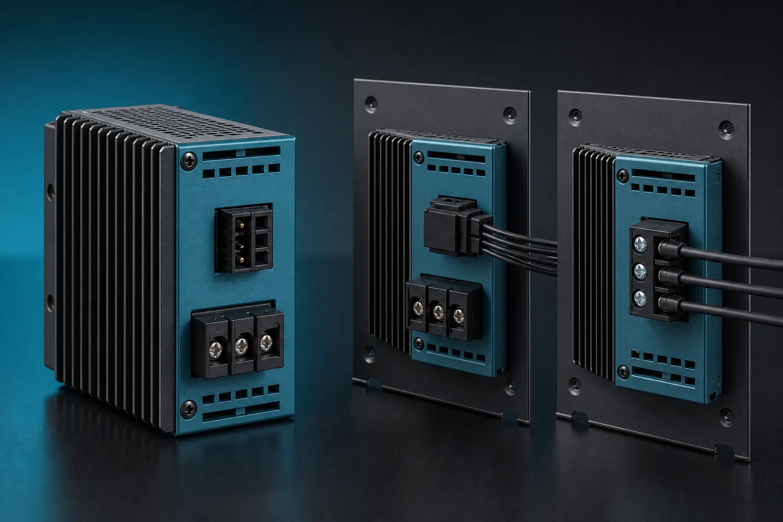
In B2B equipment sourcing, the term covers more than a plug that happens to carry current. It can describe a wire-to-wire, wire-to-board or panel interface, but the usable assembly is defined by the mated pair and its process window. That distinction helps procurement teams compare like with like across appliances, consumer electronics, EV auxiliaries, solar and storage equipment, robotics and data-center subsystems.
How do the housing, contacts, termination and lock carry power together?
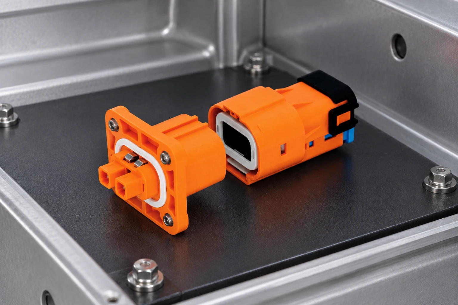
The housing positions and insulates the contacts; the contacts create the conductive path; the termination joins the contact to wire or PCB; and a locking or retention feature keeps the pair fully mated under handling, vibration or cable load. A contact system can fail even where the plastic shell appears intact: insufficient normal force, poor crimp geometry or incomplete mating can increase resistance and temperature rise. An 8-pin power connector needs these same checks; the position count does not identify the contact system.
Interface drawings should record circuit count, pitch, keying, polarization, wire range, termination style, mating cycle expectation and allowable cable pull. For example, RAST families are commonly identified by 2.5 mm or 5.0 mm pitch; pitch alone does not establish current capability, temperature performance, creepage and clearance, or approval status. IEC 60512 provides the vocabulary of test methods buyers may request, including contact resistance, voltage-withstand, mechanical operation and environmental tests.
Quick-disconnect formats such as FASTON terminals can simplify serviceable wire connections, while ring and spade terminals suit stud-based terminations. Rectangular systems often offer multi-circuit organization and keying. In every case, a specified crimp tooling and conductor preparation process is as commercially important as the nominal terminal shape, because rework, field returns and line stoppages turn a low unit price into a higher total cost of ownership.
How should power and signal requirements be separated in one interface?
A signal interface is primarily specified around signal integrity, shielding, impedance, data rate or low-level reliability; a power interface is primarily assessed around conductive path resistance, current loading, temperature rise, insulation coordination and mechanical continuity. Many assemblies contain both functions, but combining them in one housing does not erase the separate electrical requirements of each circuit.
An industrial power connector may need to withstand recurring mating, vibration, contamination or field service conditions that do not appear in a desk-top prototype. The application specification should therefore state duty cycle, ambient and local hot-spot temperature, transient behavior, installation orientation and service access. IEC 61984 is relevant to connectors intended for use in equipment, but its scope and exclusions must be checked against the actual design; it is not a substitute for product-level safety evaluation.
The supplier data sheet should distinguish a connector-family option from a validated configuration. A family may provide several housings, contact finishes, wire ranges and keys. The configuration becomes purchasable only when those selections, the mating part and the approved termination process are all identified. This is where engineering and sourcing can prevent a “same footprint” substitution from introducing an untested contact or lock combination.
What must a fit-for-use power connector specification contain?
Start with the load, then translate it into interface requirements. Record normal and peak current, voltage type, circuit count, conductor size, expected temperature range, ingress exposure, shock and vibration environment, number of mate/unmate cycles, mounting method and required approvals for the destination market. A fit-for-use specification defines acceptance evidence as well as the part. For a PCB power connector, include the board attachment and layout in that specification.
For a rectangular power connector, document the keyed mating pair, terminal part numbers, contact plating option, terminal position assurance where used and the applicable crimp height or pull-force criteria from the supplier’s controlled documentation. Verify by an agreed sample and test plan. IEC 60512 test methods can support that plan, but a selected method, severity and pass/fail limit must be stated; quoting “IEC 60512” without those details leaves too much open to interpretation.
Procurement should also ask who controls changes to resin, plating, tooling, wire preparation and production location. An illustrative calculation makes the value clear: if a modest assembly saving produces one extra line interruption or return, the avoided disruption can exceed the annual part-price delta. The calculation is illustrative, not a predicted failure rate; its purpose is to make qualification, traceability and incoming checks visible in the sourcing decision.
Which power-connection approach fits the installation and service plan?
There is no universal best interface. The right choice depends on service model, circuit density, assembly method and the evidence required for the equipment.
| Approach | Best-fit use | Strength to evaluate | Trade-off to control | TCO consideration |
|---|---|---|---|---|
| Industrial power connector with plug-and-socket contacts | Serviceable equipment and wire harnesses | Controlled mating and replacement | Match lock, key and terminal to the actual pair | Can reduce service time when parts are clearly keyed |
| Rectangular power connector system | Multi-circuit appliance, automation and control assemblies | Circuit organization and polarization | Confirm pitch, circuit loading and mating retention | May consolidate harness operations; qualify each configuration |
| FASTON quick-disconnect terminal | Accessible service connections | Fast assembly and removal | Control blade/tab compatibility and retention | Efficient where service access is designed in |
| Ring or spade terminal | Stud or screw terminations | Visible mechanical attachment | Specify torque, stack-up and anti-loosening approach | Inspection and maintenance procedure affect cost |
How should application fit, verification and compliance boundaries be documented?
| Application context | Primary interface question | Useful verification focus | Procurement evidence |
|---|---|---|---|
| Appliance and consumer electronics | Can the keyed assembly support compact routing and repeatable assembly? | Contact resistance, retention and temperature behavior | Mated BOM, work instruction and test record |
| EV auxiliary equipment | Does the selected configuration match vehicle environmental and customer requirements? | Vibration, mechanical operation and traceability | Customer-specific requirement matrix and change control |
| Solar, storage and data-center equipment | Are load profile, thermal conditions and insulation coordination defined? | Voltage-withstand and thermal assessment | Application review and declared ratings for the exact configuration |
| Robotics and industrial automation | Will cable motion and access affect lock engagement or termination strain? | Mechanical operation and cable-retention assessment | Installation constraints and service procedure |
Compliance language needs the same precision as an electrical drawing. IEC 61984 sets general safety requirements and tests for connectors within its scope; it does not automatically certify every connector marketed under a family name. IEC 60512 is a series of test methods for electromechanical components, so a report should identify the method, condition and result rather than imply a certification. UL 1977 concerns component connectors for use in data, signal, control and power applications; a UL component recognition question must be resolved for the exact component and intended end product. IATF 16949 is a quality-management-system standard for automotive production and relevant service parts, not a connector product rating.
Unsupported marks, unqualified substitutions or vague “compliant” claims can delay customer approval and create downstream liability. Destination market, end-use category and the claims made in technical literature determine what evidence is needed. Buyers should obtain current declarations, drawings and test evidence directly from the responsible supplier.
Which four checks should an OEM team complete before approving the interface?
- Freeze the mated assembly definition: housing, contacts, terminal positions, keys and termination method.
- Map electrical load and ambient conditions to an application-specific verification plan; do not infer performance from pitch or appearance.
- Qualify the wire, crimp tooling and operator/process controls alongside the purchased components.
- Request revision-controlled drawings, applicable test reports and change-notification expectations before production release.
For buyers evaluating configurable rectangular connector systems, ZUCH can be considered as one sourcing option among established connector-system manufacturers. Founded in 1994, the company serves multiple equipment markets with connectors, RAST 5.0/2.5 options, quick-disconnect terminals and related termination products. ZUCH states that it operates an IATF 16949:2016 quality-management system and has a CNAS-recognized laboratory and UL Witness Lab; buyers should confirm the applicable scope and current documentation for their exact program.
How can a buyer compare power connector types without trusting the label alone?
Use a decision sequence that moves from the application to the exact assembly. First identify AC or DC use and the voltage and current profile; then define circuit count, signal coexistence, mounting, mating cycles, environment, service access and the required safety or market evidence. Only after those conditions are fixed should a buyer compare circular, rectangular, push-pull, appliance, barrel, USB-family or other interfaces.
- Define the load and reference. Record continuous and peak conditions, polarity, return path, inrush or transients, and adjacent loaded circuits.
- Define the mechanical interface. Confirm mating half, keying, latch, pitch, mounting, cable exit and allowable strain.
- Define the process window. Match terminal, wire, crimp or solder method, tooling, inspection and repair route.
- Define the evidence. Ask for configuration-specific drawings and test records; treat standards as scoped methods or requirements, not automatic approval.
The useful comparison is therefore not “which connector looks strongest?” but “which complete, documented configuration can be validated in this product?”
What should a power-connector specification contain before comparison?
A complete specification makes competing offers comparable and exposes missing evidence early.
| Review point | Record or question | Why it closes risk |
|---|---|---|
| Electrical | Voltage, continuous/peak current, inrush, polarity and insulation | Defines the load case rather than relying on a catalogue label |
| Mechanical | Mating pair, keying, retention, mounting and cable exit | Controls fit, service and mismating risk |
| Process | Terminal/wire range, tooling, inspection and rework route | Connects the design to repeatable production |
| Environment | Temperature, moisture, vibration, contamination and life duty | Sets the validation boundary for the installed assembly |
FAQ: How should an OEM define a power connector?
What is the difference between a connector and a terminal?
A terminal is the conductive element that is crimped, soldered or otherwise joined to a conductor. A connector assembly adds the housing, mating geometry, retention and often polarization around one or more terminals. Purchase and test the mated system when the application depends on engagement and insulation.
How do engineers choose a power connector for an OEM product?
They begin with load, voltage, environment, circuit count, service life and installation constraints, then select a mated configuration that has supporting evidence. The data sheet is a starting point; the final choice also needs wire, termination and verification details.
When is a rectangular power connector a better choice?
It is often useful when several circuits need organized routing, keying and a serviceable mated interface. The selection still depends on the actual circuit load, pitch, terminal design and lock requirements, so a visual match alone is insufficient.
Does IEC 60512 certify a connector?
No. IEC 60512 describes test methods, which may be selected for a qualification plan. Ask which methods, severities, samples and acceptance criteria were applied, and evaluate whether they represent the finished equipment use case.
What documents should procurement request before approving an alternate?
Request the mated bill of materials, controlled drawings, ratings for the selected configuration, terminal and wire-process instructions, test evidence and change-control information. For automotive programs, also align those records with customer-specific requirements and the supplier’s quality-system scope.
What are the main types of power connectors?
Common categories include AC appliance interfaces, DC barrel or locking interfaces, rectangular modular systems, circular power connectors, push-pull systems and USB-family power interfaces. The category only narrows the search; the final choice still depends on voltage, current, contact system, environment, mating cycles, mounting and the evidence available for the exact configuration.
Why is a terminal only one part of a power-connector system?
A terminal is the conductive element joined to a conductor; the connector system also includes housing, mating interface, retention, keying and mounting.
Can a power connector be selected from current alone?
No. Current must be tied to the exact terminal, wire, housing, ambient, adjacent loading and duty conditions.
Does a connector standard prove whole-product compliance?
No. A connector standard or test method covers a defined component scope; the finished product still needs application and system evidence.
What should procurement request before approving a power-connector alternate?
Request the controlled mating drawings, contact and wire details, ratings for the configuration, process limits, test reports and change-control statement.
When is an organized rectangular power interface useful?
It may be appropriate when the system needs organized multi-circuit routing, keying, service access or panel integration, subject to the complete design review.
How should power and signal circuits share one connector?
Define the circuit map, insulation and separation needs, contact loading, noise sensitivity, keying and validation evidence before mixing functions.
References
- IEC 61984: Connectors — Safety requirements and tests — public scope checked 2026-10-14; it does not establish a product-specific rating, certification or application approval.
- IEC 60512-1:2018 — Connectors: tests and measurements — public scope checked 2026-10-14; it does not establish a product-specific rating, certification or application approval.
- IEC 60664-1 consolidated publication — Insulation coordination — public scope checked 2026-10-14; it does not establish a product-specific rating, certification or application approval.
- Global Electronics Association IPC standards revision table — public scope checked 2026-10-14; it does not establish a product-specific rating, certification or application approval.
Conclusion
A power connector should be approved as a complete interface, not as an isolated housing or current number. Start with the load profile and insulation boundary, then lock the mating pair, contacts, terminals, wires, keying, retention, mounting and cable route. Add the production and service process before comparing suppliers, because tooling, inspection and controlled replacement affect lifecycle risk. Use IEC 61984 for connector safety context and IEC 60512 for test-and-measurement planning, while keeping IEC 60664 concerns separate from mechanical fit. ZUCH's connector families can be reviewed against a documented application package; the finished equipment owner remains responsible for system qualification and release.