Zhejiang ZUCH Technology Co., Ltd.
When an appliance harness engineer in Stuttgart ran an illustrative pilot build, the connector mated, but one circuit opened within minutes during a light harness pull. In this illustrative scenario, the root cause was not a defective product; the team had selected by the “187” name without verifying tab thickness, terminal compatibility, and the crimp setup.
Zusammenfassung: “187” commonly points to a nominal 0.187 in (about 4.75 mm) quick-connect tab width, while IEC 61210 uses the standardized 4.8 mm size designation. That label does not define tab thickness, housing geometry, wire range, current, voltage, material, pitch, or approval status. For a 187 all-in-one connector, release the design only after the supplier drawing, mating parts, crimp specification, and application-level test plan agree.
An all-in-one format usually groups several connection points in one polarized housing so the harness can be mated as a unit. However, “all-in-one connector” is not a universal standards term. One supplier may mean a multipole housing supplied with loose receptacle terminals; another may mean a matched housing-and-header set or a preassembled harness component. The bill of materials and controlled drawing—not the product nickname—must define what is included.
What does “187” identify, and which dimensions still control fit?
The imperial shorthand comes from a nominal tab width: 0.187 in converts to 4.7498 mm, commonly rounded to 4.75 mm in industry catalogues. IEC 61210 describes 4.8 mm as one of its flat quick-connect termination sizes. Those descriptions are useful for finding a terminal family, but they do not prove that two parts will mate. A controlled interface drawing still governs the acceptable width tolerance, tab thickness, leading-edge shape, detent, insertion depth, and mating-contact geometry. These drawing checks also matter when assessing a bridge combination connector; the family name cannot establish fit.
This distinction is especially important in a multipole housing. The housing adds cavity position, center spacing, polarization, latch travel, terminal stop, contact orientation, and mating-face geometry. A receptacle that fits a loose tab may fail to seat, lock, or align inside another supplier’s housing. A product image can show a multipole housing, mating component, and terminals; it cannot establish the circuit count, material, electrical rating, pitch, certification, or exact 0.187-inch geometry.
Before comparing quotations, ask each supplier to identify the drawing revision and measurement datum. For a practical dimensional checklist, see the male tab terminal width and thickness guide. Record the width and thickness separately: matching only the “187” width can leave the spring contact either too tight, causing damage, or too loose, increasing movement and unstable resistance.
The complete assembly stack matters more than the connector nickname
A production interface is a system. Its stack normally includes the male tab or header, female receptacle contact, multipole housing, conductor, crimp, latch or secondary lock, mating component, and the tools that create and inspect the termination. A substitute is valid only when every interface in that stack has been checked.
How the tab, receptacle, housing, and crimp work together
- Tab interface: confirm nominal width, thickness, detent style, engagement length, surface condition, and alignment from the drawing.
- Receptacle contact: match the contact family to the tab and housing, then obtain the allowed conductor and insulation ranges.
- Housing: verify cavity geometry, contact orientation, keying, latch engagement, terminal retention, creepage/clearance requirements, and appliance envelope.
- Crimped termination: use the specified applicator or hand tool, strip length, crimp-height target, pull-test plan, and visual acceptance criteria.
- Mated system: test with the intended counterpart and production wire; loose-part checks do not reproduce housing alignment or harness strain.
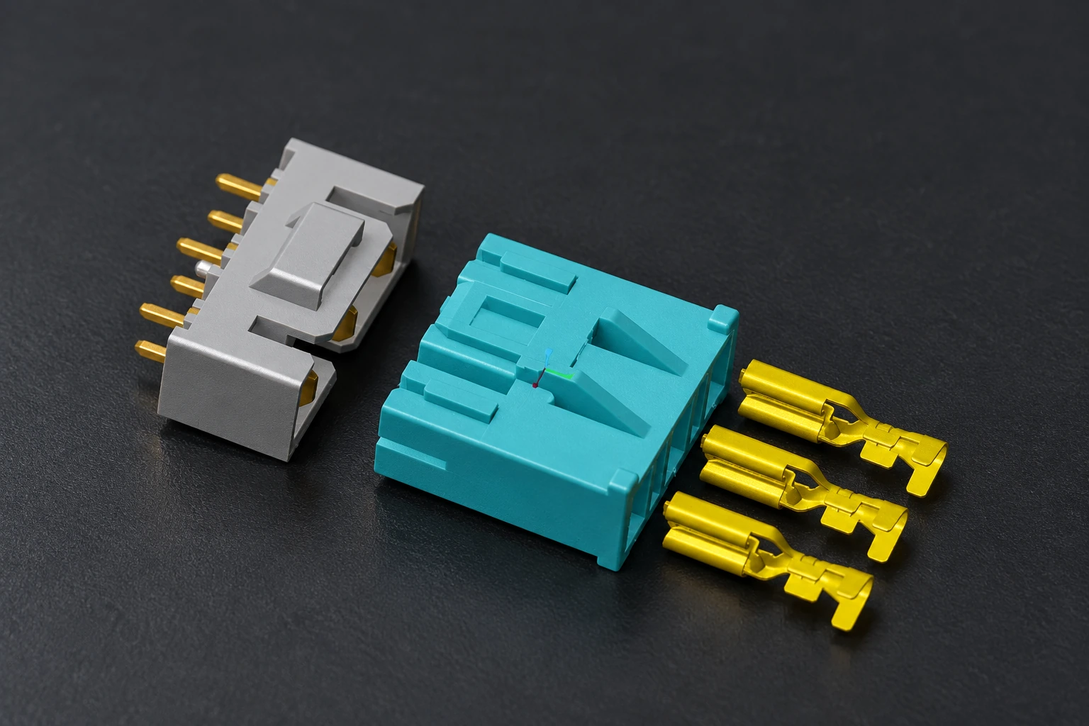
IEC 60352-2:2024 covers solderless crimped connections made with appropriately designed crimp barrels and defined wire types and sizes. It provides general requirements, test methods, and practical guidance; it does not prove that an unspecified terminal, wire, and tool combination is acceptable. Buyers should therefore request a component-level crimp specification and sample cross-sections or equivalent process evidence. ZUCH’s categories for connecting terminals and solderless terminals can help align component terminology during an RFQ, but the proposed parts still require drawing-level verification.
Which supply format gives the best production trade-off?
| Supply format | Fit and performance control | Assembly and service | Unit-cost tendency | Total-cost implication |
|---|---|---|---|---|
| Loose 187 tab and receptacle pair | Direct access to the contact interface; limited polarization | Flexible routing, but each point is connected separately | Often lower component cost | More opportunity for wiring or mating errors |
| Multipole all-in-one housing set | Keying and latch can control alignment when the full system is matched | Faster single-action mating; housing retention must be verified | More parts and tooling coordination | Can reduce line errors and service time |
| Preassembled harness connector | Supplier controls specified terminal, wire, and crimp combination | Lowest in-house assembly burden; changes require managed documentation | Higher purchased-piece tendency | Can reduce tooling, inspection, and rework if evidence is complete |
Compare landed process cost, not the connector line item alone. An illustrative 10,000-harness run with a 1% rework rate and six minutes per repair consumes 10 labor-hours before replacement parts, retest, or line disruption are counted. Use your own defect rate and burden rate; the point is that a slightly cheaper contact can be uneconomic if the tool window or mating controls are weak.
A drawing-led selection workflow prevents most compatibility errors
- Define the application boundary. State circuit functions, conductor sizes, duty cycle, ambient conditions, mating frequency, available space, service access, and destination market. Do not copy a catalogue rating into the requirement without its test conditions.
- Freeze the interface. Obtain the tab, receptacle, housing, and mating-component drawings. Confirm every critical dimension and the drawing revision.
- Approve the termination process. Specify wire construction, strip length, applicator, crimp height or other process controls, insulation support, and acceptance sampling.
- Build representative samples. Use production-intent wire, tooling, housing, and mating parts; inspect seating and locks before electrical and mechanical testing.
- Control procurement evidence. Put part numbers, revisions, approved alternates, inspection records, lot traceability, and change-notification expectations into the sourcing package.
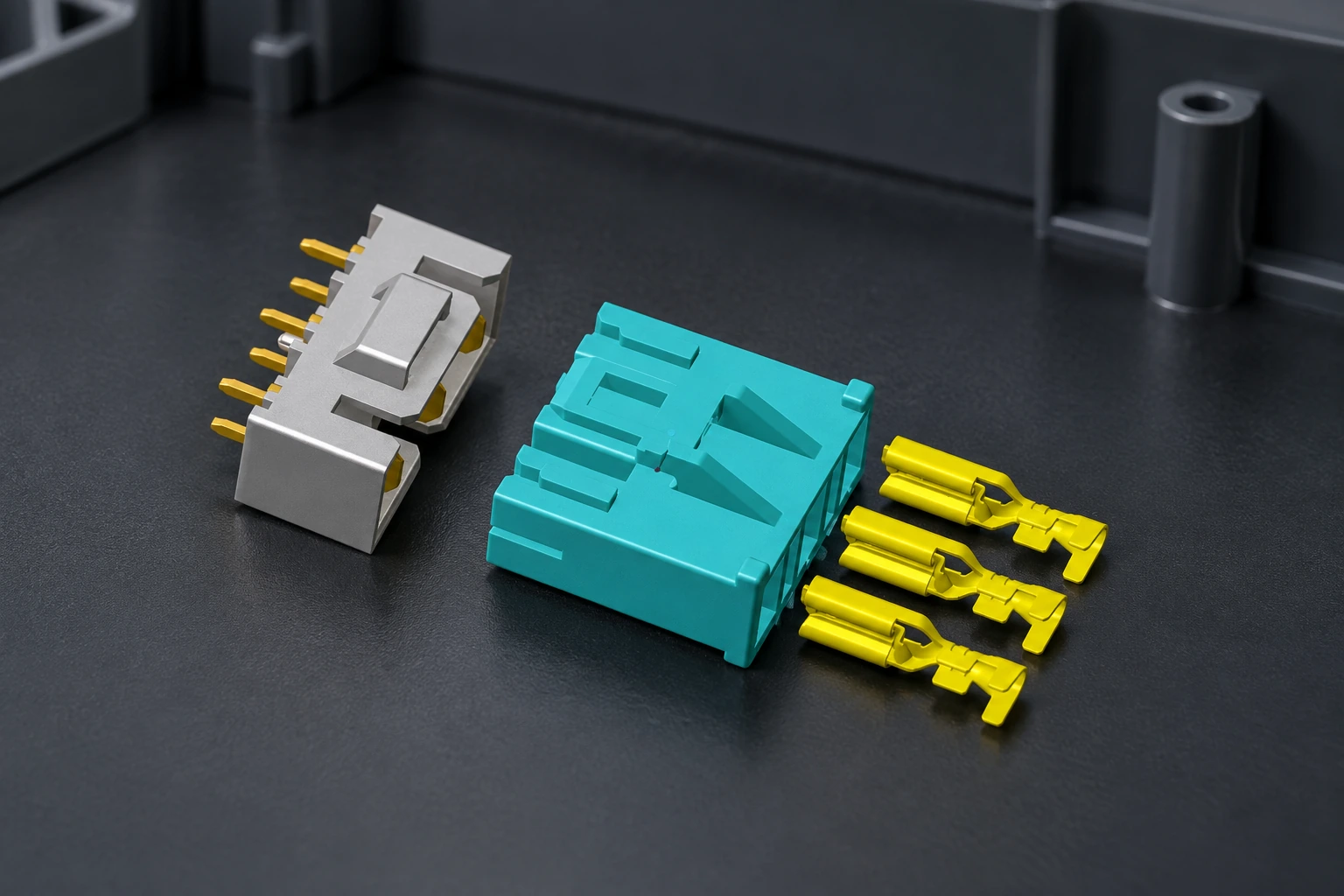
Contact resistance deserves special attention because the interface includes the tab-to-receptacle contact and the wire-to-terminal crimp. IEC 60512-2-1 defines a millivolt-level method for measuring resistance across mated contacts or a contact and gauge. It is a test method, not a universal pass limit; the product specification must state test points, conditioning, sample size, and acceptance criteria. See this explanation of how contact resistance affects connector performance before setting the validation plan. For RAST connectors, too, the test conditions and acceptance criteria must match the exact product.
| Verification point | Evidence or test | Likely failure if omitted |
|---|---|---|
| Tab width and thickness | Controlled drawing plus dimensional inspection | High insertion force, weak normal force, or incomplete engagement |
| Terminal-to-housing retention | Seating check, secondary-lock check, and specified axial retention test | Contact backs out during mating or service |
| Crimp process | Tool record, crimp dimensions, visual check, and conductor pull test | Broken strands, loose conductor, or intermittent circuit |
| Mated electrical path | Baseline and post-conditioning resistance using a defined method | Undetected heating or voltage-drop risk |
| Production environment | Application-specific temperature, vibration, cycling, and contamination plan | Bench fit passes, but field duty causes fretting, loosening, or insulation damage |
Standards define scope and methods, not automatic product approval
IEC 61210:2010 applies to specified non-insulated flat quick-connect terminations, including 4.8 mm tabs and mating female connectors, and sets dimensional, performance, and test-program requirements within its stated conductor and application scope. Use it when the termination falls inside that scope; do not cite it as proof for an entire multipole assembly without matching evidence.
UL 310 covers quick-connect tabs and connectors with nominal widths including 4.8 mm (0.187 in). Its public scope also states that multi-pole devices are not covered there and points those devices to UL 1977 and the corresponding Canadian standard. That boundary is commercially important: a terminal claim cannot be silently extended to the complete housing assembly. Destination market, end-equipment standard, and the exact construction determine which evaluation applies. Nothing in this guide implies that the pictured product or any ZUCH product is certified to these standards.
Frequently asked questions about 187 all-in-one connectors
Is every 187 connector interchangeable?
No. The nickname may indicate a nominal tab width, but thickness, detent geometry, receptacle spring design, housing cavity, keying, and latch can differ. Approve interchangeability only from both suppliers’ controlled drawings and representative mating tests.
Does “187” mean the connector is rated for a particular current?
No. Width alone does not establish current capacity. Ask for the rating conditions, conductor size, temperature-rise limits, loaded-circuit assumptions, derating information, and application test evidence.
Is 0.187 inch exactly the same as 4.8 mm?
Mathematically, 0.187 in is about 4.75 mm; IEC and UL scope language uses a nominal 4.8 mm designation for this size family. These labels are nominal, so the drawing tolerances and tab thickness still control mating.
Can a product photo confirm the circuit count and terminal specification?
No. A photo may show the general architecture, but perspective and rendering do not establish cavities, pitch, dimensions, material, plating, or ratings. Request a part-numbered drawing and bill of materials.
What should an OEM send with an RFQ?
Send the mating drawing or sample, wire specifications, circuit and load matrix, environmental profile, annual volume, assembly method, compliance market, and required test documents. Mark critical characteristics and identify whether the supplier must provide loose components or a finished harness assembly.
Authoritative references
- IEC 61210:2010 — Flat quick-connect terminations: safety requirements and scope
- IEC 60512-2-1:2002 — Contact resistance, millivolt-level method
- IEC 60352-2:2024 — Solderless crimped connections
- UL 310, Edition 10 — Electrical Quick-Connect Terminals
- Newark industry catalogue — 4.75 mm and 0.187 in quick-disconnect size terminology
The reliable rule is simple: use “187” to start the search, and use drawings, tooling records, and test evidence to finish the decision.
For a ZUCH sourcing review, share your mating interface, wire range, annual volume, assembly method, and required documentation. Contact ZUCH to discuss a drawing-led connector and terminal proposal before releasing production tooling.