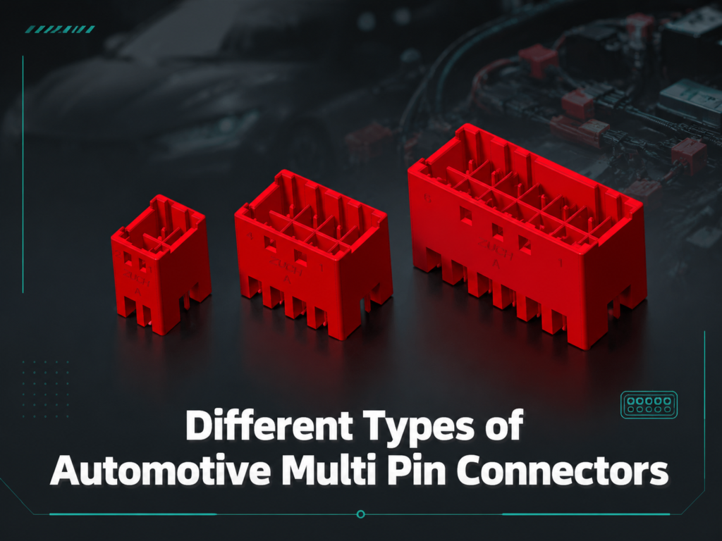
Different Types of Automotive Multi Pin Connectors
Automotive Multi-pin connectors are a key part of all today’s vehicles. They allow for ease of electrical and electronic power transfer from one system to another and signal/data transfer between the different electrical and electronic systems. If you are either designing new electrical systems or diagnosing existing electrical connections, you need to know what automotive multi-pin connectors are available and their purpose. By knowing what types of automotive multi-pin connectors are available, their characteristics and where they can be used, you will be able to make an educated decision on which connector to use for a specific application.
Multi Pin Connectors Explained
A multi-pin connector is an electrical connection device used to connect multiple wires to a single connection point. Each pin passes power, a signal, or data between the devices. Multi-pin connectors provide the critical means of allowing reliable communication and transfer of power between each of the devices in an automotive electrical system. They can be used to connect various devices; for example, a sensor, control module (ECU), light or infotainment module could be connected through multi-pin connectors.
Most Common Types Of Automotive Multi Pin Connectors
There are many types of automotive multi-pin connectors and they all can be categorized by their shape, size and potential application. The following is a list that explains some of the more common types of automotive multi-pin connectors:
Multi-Pin Circular Connector
Multi Pin Circular Connectors are, as the name implies, circular in shape and make it easy to mate and separate. They are widely used in automotive applications because they are very strong and durable, providing a stiff seal that protects against moisture, dirt and vibration. Multi Pin Circular Connectors are useful in harsh environments such as in engine compartments under the vehicle where water resistance is important.
Multi-Pin Rectangular Connectors
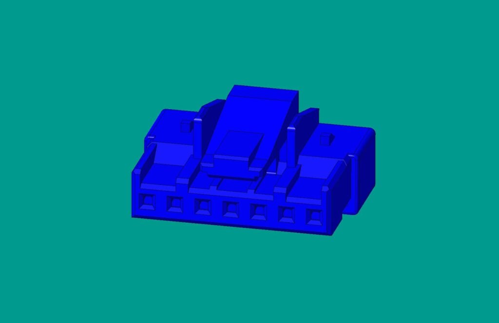
Rectangular connectors are frequently seen in automobiles and have a distinct advantage due to their rectangular shape, including improved flexibility in both pin configuration and layout. Rectangular connectors are compact and provide high pin densities, which makes them well suited for difficult-to-access locations in automobiles.
Multi-Pin ‘D’ Shaped Connectors
D-shaped connectors (or D-Sub Connectors) have a secure locking mechanism, compact design, and are shaped like the letter “D,” making them easy to connect in the proper orientation (no more guessing!). D-shaped connectors are often used in data transfer systems, making them an essential component in an automobile’s complex electronics.
Automotive Multi-Pin Connector Pin Count Configurations
The number of pins (or terminals) determines categorization for multi-pin connectors. For example, this includes 2-pin, 3-pin, and 4-pin connectors, as well as applications for each type. The pin count also determines how complex the connection and functionality will be for any connector(s). The following sections detail the various pin count configurations for multi-pin connectors frequently seen in an automotive application and possible uses for them.
2-Pin Automotive Connector
The 2-pin connector is the most basic form of a multi-pin connector used in automotive wiring applications and is typically utilized for single-function devices including automotive headlights, taillights, or simple sensors. Because the design is very simple and has limited wiring required, they are easy to install and result in less complexity of wiring.
3-Pin Automotive Connector
Automotive 3-pin connectors are typically used in systems that provide an additional wire for control or signal purposes (i.e., brake light sensor, throttle position sensor, and fan motor control).
4-Pin Automotive Connector
The 4-pin automotive connectors, used on prime power, are a 4-pin version of the 3-pin connectors and are typically used for devices requiring two power and two signal wires (light circuits, relay-switch circuits).
6-Pin Automotive Connector
The 6-pin automotive connectors are designed for moderate complexity and typically are used to connect moderately complex sensors or control circuits. They allow for power and multiple types of signals.
8-Pin Automotive Electrical Connectors
Used for more advanced applications that require multiple input and output connections like in the electrical control of mirrors, advanced infotainment, and complex throttle control.
10-Pin Automotive Electrical Connector
There are 10 pins in an automotive electrical connector; they typically are used in applications like automatic transmission control modules and multi-sensor networks. A higher pin count means flexibility and functionality.
12-Pin Automotive Connector
These connectors are for very complex automotive systems. They are primarily used in very important vehicle subsystems like advanced driving systems (ADAS), engine management systems, and other critical subsystem circuit systems. They allow for simultaneous electrical power supply and many different data signals to be transmitted.
In order to select the best configuration for your application’s pin count and level of functionality needed, when wiring a coupler to an electrical component (i.e., power to a simple light), one may only require a 2-pin automotive connector. Conversely, for multi-pin connectors built for complex applications, like an onboard diagnostic tool, a 12-pin automotive connector may be the preferred connector style.
Automotive Connector: General Information
In order to effectively use automotive multi-pin connectors, the selection, installation and maintenance of an automotive multi-pin connector is very important. Some practical tips to get started with automotive multi-pin connectors are:
Selection of a connector:
Always use the specific requirements needed for your application when selecting a connector. Some of the actual requirements are: number of pins needed, shape and material of connectors. Also, make sure your connector can be connected to the electrical or electronic components you are going to connect to.
Inspection and cleaning:
After time passes, dirt, moisture and oxidation can build up on connectors, resulting in poor conductivity or connection failure. Regular inspections and cleanings of connectors using proper electrical contact cleaner can eliminate these types of problems.
Properly mating and locking connectors:
When mating electrical connectors, properly secure the connector with a locking mechanism or similar methods to ensure that no accidental disconnection occurs and no external contaminant (dirt and/or water) will be able to get into the electrical connectors.
Wire prep:
When attaching wires to pins, use the correct tool to ensure the wires are properly stripped and crimped. Use of proper tools prevents damage to the connector as well as creating a solid connection between the connector and the wire.
Frequently Asked Questions (FAQs)
How Do I Use A Multi-Pin Connector In An Automobile?
To utilize multi-pin connectors for automobiles properly, perform the following:
- Identify the type of connector and corresponding number of pins (e.g., you cannot use a 3-pin connector in place of a 2-pin connector in most circumstances).
- Prepare the wires by stripping the insulation off and securely attaching it to the pins with appropriate crimping tools.
- Ensure that all the pins are aligned correctly and seated securely before locking the connector into place.
- Inspect and clean connectors regularly to avoid any possible issues caused by corrosion or dirt buildup which could impede function.
What Are Common Uses For Multi-Pin Connectors In Automobiles?
Multi-pin connectors are used extensively throughout a vehicle’s systems, including:
- Engine Control Module (ECM) and Transmission Control Module (TCM)
- Advanced Driver Assistance System (ADAS)
- Infotainment/Audio System
- Exterior/Interior Lighting (e.g., headlights and taillights)
- Temperature Sensors/Pressure Contactors/Monitor Applications
- Powertrain Components/Fuel System Components
How Do I Fix Any Issues With Multi-Pin Connectors In Automobiles?
If you experience issues with the use of an automotive multi-pin connector, follow these steps to help determine the cause of the problem:
- Visually inspect for any damaged or loose pins creating a possible break in continuity.
- Visually check the wire for any damaged, corroded, or broken wire.
- Use an appropriate electrical contact cleaner to clean the connector and remove dirt and oxide buildup.
- Verify that the connector is properly seated and locked in place.
- Use an ohm meter or multi-tester to check continuity and ensure there are no issues with current flow between the two mating surfaces.
How Do I Find The Best Multi-Pin Connector For My Vehicle?
When choosing which connector will best suit your needs, consider the following:
- Total amount of pins required for your application.
- Shape and size of the connector; must fit through the hole for installation.
- Outdoor/Indoor applications such as moisture, heat, and vibration.
- Expected allowed current carrying capacity and signal handling capability of the connector.
- Quality of material and construction of the connector.
If you have further questions or are not sure what type of connector to use, it is always wise to consult the technical specification documents for your components or ask someone knowledgeable.
In conclusion, multi-pin connectors play an important role in today’s vehicles because of their versatility. Knowing about the variety of types, shapes, and configurations associated with these connectors, in addition to the various usages, will allow you to achieve optimal performance when using them as part of your vehicle’s systems. Selecting the correct connector is essential for having a reliable and efficient automotive application, whether it is a simple two-pin connector or a more complex twelve-pin connector.
Does a higher pin count always mean a better automotive connector?
No. More positions can reduce harness branches, but they can also increase packaging, routing, mating force, circuit separation, and service complexity. Select the smallest controlled interface that meets the documented circuits and environment. For a related technical topic, see Automotive Electrical Harness Connectors.
Can I replace a six-pin automotive connector with an eight-pin connector?
Only after an engineering review confirms the housing, mating half, keying, terminals, seals, cavity map, mounting space, and validation requirements. A higher position count is not an electrical adapter and should not be treated as one.
Are all positions in a multi-pin automotive connector electrically equivalent?
No. Positions may use different terminals, wire sizes, seals, circuit functions, or electrical duties. Record each cavity individually and do not infer current capacity from the housing position count.
How do I read the pin numbers on a multi-pin connector?
Use the released connector drawing and mark whether it shows the mating face or the wire-entry face. Add the latch or key orientation and cavity 1, then verify several non-adjacent cavities before mapping the remaining positions.
When should I choose a sealed multi-pin connector?
Choose sealing from the actual exposure boundary, including splash, wash, dust, salt, condensation, fluid contact, and service conditions. Confirm the housing seal, wire seals, cavity plugs, rear cover, and mating part as one system.
What should I send a supplier when asking for a multi-pin connector recommendation?
Send the mating drawing or photos, cavity map, populated and spare positions, wire gauge and insulation diameter, current and signal requirements, keying and mounting constraints, exposure, service cycles, and required test evidence. This prevents a pin-count-only recommendation.
Engineering Update: Pin Count Is a Starting Point, Not a Compatibility Specification
A two-, six-, or twelve-position housing describes available cavities, not the circuit function, current capacity, pinout, terminal family, or mating half. A connector with the same position count may still be incompatible because its keying, cavity pitch, latch, contact size, wire range, sealing, or view orientation differs. The safe selection unit is the complete interface: housing, mate, terminals, seals, locks, wire, application, and released drawing.
| Selection layer |
Question |
Evidence to keep |
| Geometry |
What are the housing outline, pitch, cavity layout, key, latch, and mounting constraints? |
Supplier drawing and mating-face and wire-side views |
| Circuits |
Which positions carry power, ground, signals, data, shielding, or remain unused? |
Controlled cavity map and circuit list |
| Contacts |
Which terminal family, contact sex, conductor range, plating, and crimp tooling are approved? |
Terminal drawing and application specification |
| Environment |
Will the interface see splash, salt, dust, heat, vibration, condensation, or service handling? |
Exposure definition, seal system, and applicable test plan |
| Validation |
How will fit, retention, continuity, isolation, and environmental performance be accepted? |
Inspection and test records tied to the same revision |
How to Choose a Multi-Pin Connector Step by Step
- List the required circuits and separate populated, spare, blocked, and cavity-plug positions.
- Choose the housing family from the installation envelope and the mating component, not from pin count alone.
- Declare the connector view used for cavity numbering. Mating-face and wire-entry views can mirror a two-row layout.
- Match each terminal and wire seal to the conductor and insulation diameter, then document crimp tooling and retention checks.
- Confirm keying, polarization, primary and secondary locks, strain relief, and service access before ordering samples.
- Test the assembled interface for continuity, unintended shorts, retention, mating operation, and the environmental conditions defined by the program.
References and Further Reading
- ISO 8092 road vehicles — connections for on-board electrical wiring harnesses
- TE Connectivity automotive connector systems
- Amphenol LTW, Types of Multi-Pin Connectors
- IPC/WHMA-A-620 cable and wire harness acceptance resource
 Zhejiang ZUCH Technology Co., Ltd.