Wire Harness Branch Design: Choosing Splices, Junctions and Breakouts
Define the harness architecture and verification plan before comparing an assembly approach. Use the controlled drawing, actual operating conditions, and approval requirements.
Inhalt
What defines a wire harness branch?
A branch is a controlled split in the harness architecture, not merely a place where wires separate. Define each circuit path, branch length, protection, support point, and assembly sequence before comparing a splice, junction, or breakout approach. For a related technical reference, see Wire Harness Electrical Testing: Continuity, Hi-Pot and Contact Resistance Explained.
| Review area |
Buyer needs to define |
Why it matters |
| Controlled configuration |
Drawing, interface, and operating condition |
Prevents a generic answer from becoming a release decision |
| Mechanical architecture |
Routing, protection, fixture, and service constraints |
Reveals physical conflicts early |
| Acceptance evidence |
Samples, methods, limits, and records |
Makes supplier and engineering reviews comparable |
When does an inline splice fit the branch?
An inline splice can suit a defined conductor transition where access, insulation restoration, protection, and inspection are controlled. It is not a substitute for a junction when the design needs multiple outputs, serviceability, or a documented distribution point. For a related technical reference, see Butt Splices vs Terminal Splices: How to Select an Inline Wire Connection.
When should a junction be specified?
Use a junction concept when several circuits need a defined distribution location, enclosure interface, or service boundary. Record the connection method, identification, protection, sealing, and the mechanical envelope around the branch.

How do breakouts change routing?
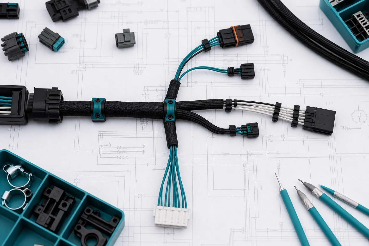
A breakout creates multiple managed paths from a trunk. Review bend radius, exit direction, clamp positions, branch length tolerance, abrasion protection, and whether cable movement or service access can load the branch point.
What process details should be controlled?
Specify drawing revision, conductors, splice or junction components, protection method, assembly sequence, fixture access, inspection points, and the reaction route for a nonconforming branch. Do not allow a field-friendly repair concept to become an unapproved production method.
Wichtig: General guidance cannot approve a finished harness. This is a source-note application of the IPC and TE references below; use the controlled drawing and programme acceptance plan.
What should be validated before release?
Validate the representative branch configuration in the intended routing envelope. The plan should define samples, visual and electrical checks as applicable, acceptance criteria, records, and change triggers.
Which ZUCH route supports a controlled inquiry?
Use ZUCH’s Home Appliance solution route and the live product catalogue to identify relevant connector or terminal component families. These are discovery routes only and do not demonstrate a finished harness is approved.
RFQ inputs
- Controlled drawing, revision, interface, and circuit definition.
- Routing, environment, service, and mechanical constraints.
- Required samples, inspection/tests, acceptance criteria, and records.
- Change-control and nonconformance expectations.
Fit Boundary
This guide supports engineering and sourcing discussion; it cannot replace programme-specific validation, market requirements, or an approval record. Use ZUCH’s sample request route or contact page for controlled component documentation and samples.

Choose a branch architecture from circuit ownership and routing risk
A branch drawing should make the current path, breakout location, support method, and service boundary unambiguous. An inline splice, a junction, and a breakout are not just different names for the same geometry: they assign different responsibilities for joining circuits, routing the harness, and controlling stress.
| Architecture |
Use it when |
Design evidence to show |
| Inline splice |
Two or more conductors join within the harness and do not need a separate service interface |
Splice location, wire range, insulation/support and crimp process |
| Junction or distribution point |
Several circuits need a defined common or distributed interface |
Circuit map, cavities/terminals, service access and protection |
| Breakout |
A main bundle divides into branches with controlled routing |
Reference datums, branch lengths, bend zones, tie points and strain relief |
| Overmold or sealed branch |
The branch boundary needs a defined environmental or mechanical transition |
Material, geometry, sealing scope and validation evidence |
FAQ
When should I use a splice instead of a junction?
Use an inline splice when conductors simply need to continue or join inside the harness. Use a junction when the interface, distribution, service access, or circuit identification needs a defined multi-connection boundary.
Why are breakout lengths important?
They control fit, bend radius, branch routing, and strain at the terminals. A harness can pass continuity and still fail installation if breakout dimensions are uncontrolled.
Does a branch need strain relief?
Any branch exposed to pull, vibration, repeated movement, or connector weight needs a defined support strategy. The drawing should show the support location and the protected bend transition.
What should be shown on a branch drawing?
Show circuit identity, splice or junction part numbers, branch reference points, lengths/tolerances, orientation, bend zones, labels, protection, test points and revision-controlled accessories.
What is a wire harness branch?
It is a designed point where one harness path divides into controlled circuit paths, with defined routing, protection, and connection requirements.
When should I use a splice instead of a junction?
Use the architecture that fits the required number of paths, access, protection, service need, and approved assembly method. The drawing should make the decision explicit.
Why are breakout lengths important?
They affect installation reach, bend and clamp locations, service access, and strain at the branch point.
Does a branch need strain relief?
The branch and its surrounding cable need support appropriate to the routing and expected movement, so load does not concentrate at the connection.
What should be shown on a branch drawing?
Show circuit paths, branch location, components, dimensions, protection, clamps, identification, inspection, and release requirements.
How should a branch be tested?
Use the controlled test plan for the actual configuration. Electrical and visual checks should be tied to the drawing and acceptance criteria.
What belongs in a harness branch RFQ?
Include the controlled drawing, conductor and component definitions, branch geometry, protection, routing, test plan, samples, records, and change-control needs.
Key takeaway
A harness branch is ready for release when its circuit ownership and physical routing are both explicit. Select splice, junction, breakout, and protection features together, then validate the installed path rather than continuity alone.
References
 Zhejiang ZUCH Technology Co., Ltd.