Zhejiang ZUCH Technology Co., Ltd.
In a typical harness drawing review in Nagoya, a harness engineer approved a 30-cavity connector after checking only the catalogue photograph and the headline cavity count. The first build showed a rapid, visible failure: the continuity tester reported several circuits in the wrong positions because the drawing used the wire-entry view while the assembly sheet used the mating-face view. The connector had not suddenly become defective; the selection process had left the interface, lock state and terminal map undefined.
Resumen: Select a 30 pin automotive connector as a controlled 30-position system, not as a housing with “30” in its name. Freeze the viewing orientation, map every cavity, match both housings and approve the terminal, wire, seal and lock combination. ISO 8092 and SAE/USCAR-2 address automotive harness-connection performance in different ways, while IEC 60512 supplies test methods; none is a blanket certification for an unspecified assembly. Release a representative sample only after position-by-position continuity, isolation and mechanical checks are defined.
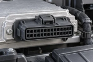
A 30-position interface is useful when a body, door, seat, HVAC, lighting or control-module harness needs many circuits through one serviceable connection. The number describes available cavities; it does not tell procurement which positions are populated, which contact size is permitted, or whether the interface is sealed. The released harness drawing and connector family documentation must answer those questions.
Why does a 30-circuit interface require a drawing-led selection?
Thirty positions can consolidate power, grounds, sensor lines, actuator outputs and communications. That consolidation can simplify routing, but it also concentrates the consequence of one wrong cavity or partly seated terminal. A good review starts with a 30-row cavity schedule tied to the schematic, wire list and assembly instruction.
For each row, record circuit function, wire and insulation dimensions, terminal family, seal or cavity plug, keying, and the intended lock state. Mark positions as populated, intentionally empty or blocked. “30-way” is not a promise that every cavity accepts the same terminal or that every visible cavity should receive a wire.
Declare the view directly on the drawing: for example, “mating face, latch up, cavity 1 at upper left.” Wire-entry and mating-face views are mirrored. Reconcile the map across the harness drawing, work instruction, test fixture and service information before a supplier quote is compared.
Do not approve an original or alternate connector from a “30-position” label, a product photograph or a marketplace vehicle-compatibility statement. The label establishes only a position count; a photograph can hide the terminal system, seal package and secondary-lock geometry; and a compatibility claim may omit vehicle build variation, module revision and viewing convention. Instead, assemble an identification pack from the connector-family drawing and the applicable module or vehicle documentation: record both housing numbers and revisions, the connector face orientation, cavity-numbering view, key and latch geometry, populated and intentionally blank cavities, terminal family, secondary lock, interface and wire seals, cavity plugs, and conductor and insulation data.
For an alternate, compare that pack line by line with the candidate supplier’s controlled drawings, then inspect a representative mated pair and harness sample. Confirm keying and lock travel without forcing the parts, reconcile all 30 positions with the released schematic, and perform the programme-defined continuity, isolation and mechanical checks before approval. If the evidence cannot resolve one of those interface attributes, treat the alternate as unconfirmed rather than inferring fit from appearance.
How should engineers confirm terminal layout and serviceability?
How do you distinguish 30 available cavities from the circuits actually populated?
A 30-cavity housing can be fully populated, partly populated with controlled reserves, or built with blocked or sealed vacant positions. Empty positions still need an instruction: leave open only where the application allows it, or install the specified cavity plug. This prevents a service technician from adding an unapproved contact or removing a seal that the validation build relied on.
Some families allow more than one contact size, but a cavity is not interchangeable merely because the terminal fits by hand. Approve the terminal, conductor cross-section, insulation diameter and crimp tooling for every populated position. The contact assignment should also reflect the circuit duty and any signal-integrity constraints defined by the vehicle programme.
How should retention, secondary locking and service access be controlled?
Primary retention holds an individual terminal in its cavity. A secondary lock or terminal-position assurance feature confirms seating; a connector-position assurance feature may secure the mated latch. These functions are related but not identical. Document insertion orientation, the pre-lock and final-lock positions, the visual confirmation and the approved removal tool.
Serviceability is part of selection, not an afterthought. A technician should be able to identify cavity numbers, release a terminal without damaging the housing, install an approved repair contact and restore the lock. A single-terminal repair may be acceptable when the vehicle or module service information permits it, the exact terminal, seal and tool are available, the cavity still retains the contact, the secondary lock closes correctly, sealing surfaces remain sound and the repaired circuit can be retested. Replace the housing—or the larger service assembly required by the programme—when cracking, heat distortion, damaged keying or latch features, weakened cavity retention, a broken secondary lock, or damaged interface sealing prevents restoration to the documented condition. Corrosion or overheating extending beyond one contact also requires programme-specific investigation rather than an automatic one-terminal repair. ZUCH’s guide to positive-locking terminals and secondary retention is useful background when defining that inspection sequence.
Why must matching male and female housings be approved together?
A 30 pin automotive connector is a mated system: two keyed housings, compatible contacts and, where required, seals, cavity plugs, locks, strain relief or a lever. Equal cavity counts and a latch that appears to close do not prove contact overlap, key compatibility, terminal retention or correct sealing.
Control both housing part numbers and revisions, the mating-face drawing, key code, cavity numbering, terminal family and plating specification. “Male” and “female” can refer to contacts or housing halves, so use manufacturer part numbers rather than informal labels. Check that the mate is the released pair, not a look-alike with the same number of cavities.
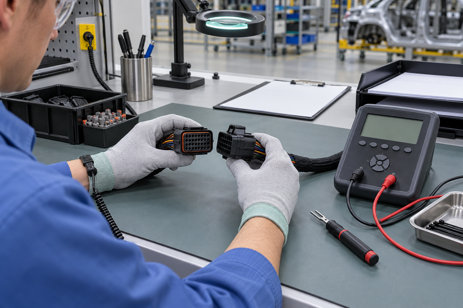
Then test the actual harness build. A representative assembly should be checked for cavity-to-cavity continuity, adjacent-circuit isolation and any loaded voltage-drop or signal test required by the programme. A connector that clicks is mechanically engaged; it is not automatically electrically correct.
Should the connector be sealed or unsealed?
Choose sealing from the installation zone and exposure, not from a generic “waterproof” listing. A protected cabin module may prioritise keying, strain relief and service access. A door, seat or engine-compartment interface may add movement, fluids, heat, condensation or contamination. An exterior or underbody position usually needs a validated sealed system, cavity plugs and a service method that restores the seal.
“Sealed” is not a stand-alone performance result. The environmental outcome belongs to the tested mated assembly with its actual wires, insulation, seals, plugs, backshell or strain relief and mounting. Define the exposure and test sequence; do not transfer an ingress claim from one configuration to another.
| Selection option | Best-fit use case | Evidence to request | Typical risk if undocumented |
|---|---|---|---|
| Unsealed matched system | Protected cabin or enclosed module, when the application allows it | Paired housings, cavity map, terminal and lock instructions | Wrong pinout, fretting or difficult service |
| Sealed matched system | Exposure to water, dust, fluids or condensation, subject to validation | Seal range, cavity-plug rules, mated-build test plan and repair method | Leak path after incorrect seal or repair |
| Mixed-terminal 30-cavity family | Harnesses with different circuit duties, only where the family permits it | Cavity-by-cavity terminal, wire and crimp compatibility | Contact mismatch or overload from a visual fit |
| Service-oriented housing | Modules likely to be disconnected or repaired in the field | Depinning tool, replacement contacts, lock-state and inspection data | Housing damage, back-out or unverified repair |
An illustrative total-cost check should include drawing control, samples, tooling, end-of-line testing, rework and service. If 1% of 10,000 harnesses required 20 minutes to diagnose and repin, the intervention would consume about 33 labour-hours before line disruption or retest. This is not a defect forecast; it demonstrates why clear interface evidence can outweigh a small initial unit-price difference.
What matching evidence should procurement review for terminals, wires and the complete interface?
There is no universal “30-pin wire gauge.” The family may support one contact system or several, and each terminal has a specified conductor range, insulation diameter, crimp geometry and retention requirement. Select by the released circuit load and wire construction, then verify the terminal drawing and crimp specification.
For procurement, require a table that links each populated cavity to its terminal part number, conductor cross-section, insulation range, seal (if any), crimp tooling and inspection method. Avoid replacing a terminal with one that merely shares the same nominal blade width. Contact geometry and retention belong to the approved family. The following matrix turns a product-led quote into a release decision: each row needs traceable evidence and an acceptance result, not a sales description.
| Matching evidence | Release record required | Approval check |
|---|---|---|
| Housing identity and orientation | Both housing numbers and revisions; mating-face and wire-entry drawings; latch-up reference; cavity-1 location; key code | The candidate is the documented mating pair, and its face orientation, numbering view and keying match the released interface without force. |
| Cavity population | A 30-row schedule marking every position as populated, intentionally blank, plugged or blocked, linked to the schematic and tester file | The supplier sample and test fixture reproduce the same population and numbering; no blank cavity is assumed to be unused or open. |
| Terminal and wire | Terminal family and part number by populated cavity; conductor cross-section; wire construction; insulation diameter; crimp tool and inspection criteria | Each terminal and wire combination falls within the family documentation and the programme’s released circuit requirements. |
| Retention and secondary lock | Terminal insertion orientation, primary-retention check, secondary-lock part and pre-lock/final-lock positions | Contacts retain in their cavities, the secondary lock reaches its documented final position and removal remains possible with the approved tool. |
| Seal package and environment | Interface seal, individual wire seals, cavity plugs, supported insulation ranges, strain relief and installation-zone validation plan | The representative build contains the specified seal parts and actual wires and completes the programme-defined environmental sequence. |
| Module and vehicle evidence | Applicable module drawing, vehicle schematic, connector identifier, build or revision applicability and authorised service information | The connector assignment and repair method agree across supplier, harness, module, vehicle and service documents; unresolved conflicts stop release. |
For broader context on harness architecture, see ZUCH’s overview of automotive electrical harness connectors. It should complement—not replace—the connector family drawing and the vehicle programme’s circuit requirements.
Which standards belong in the validation plan?
- SAE/USCAR-2 is an automotive performance specification for electrical connector systems. State the revision, sample configuration, conditioning, test category and limits; citing the document does not prove that an unspecified 30-cavity assembly passed.
- ISO 8092-2 addresses connections for on-board road-vehicle electrical wiring harnesses within its defined scope. Confirm the applicable edition, voltage class, customer additions and actual component build.
- IEC 60512 provides connector test methods, such as electrical, mechanical and environmental test procedures. A test-method reference is not a product certification or a claim that every test applies to every vehicle interface.
- IEC 61984 sets safety requirements and tests for connectors in its stated voltage and current scope. It should not be presented as a blanket automotive certification, particularly for low-voltage harnesses outside that scope.
Standards become commercially meaningful when the purchase specification names the edition, test category, sample build and acceptance limits. Unsupported compliance language can lead to an approval-package rejection, repeat testing or a customer claim even when the plastic housing looks correct.

What should procurement release before choosing a supplier?
- Freeze the interface: issue both housing numbers, keying, revisions, mating orientation and cavity numbering.
- Control all 30 positions: list function, wire, terminal, seal or plug, intentional vacancies and blocked cavities.
- Define assembly: state insertion orientation, primary and secondary lock positions, crimp tooling and inspection evidence.
- Match validation to location: define movement, temperature, fluids, moisture and the applicable standard or customer test plan.
- Plan repair: identify removal tools, replacement terminals, cavity-seal parts and the required continuity and isolation retest.
ZUCH can review a connector enquiry against the interface evidence supplied by the buyer. Include the 30-position circuit map, mating details, wire and insulation data, installation zone, service expectations and required validation; a product photograph alone is not enough to establish compatibility.
Frequently Asked Questions
What is a 30-pin automotive connector typically used for in large wiring harness sections?
It can consolidate up to 30 defined cavities for power, ground, sensor, actuator or communication circuits serving a body, door, seat, HVAC, lighting or control-module section. Confirm the actual circuit population and duty from the vehicle drawing; the cavity count alone does not identify the application.
How do I confirm that a 30-pin automotive connector matches my vehicle wiring?
Compare both housing part numbers, keying, viewing orientation, cavity map, terminals, wire and insulation dimensions, seals and lock features. On a representative harness, verify every assigned circuit by continuity, adjacent-circuit isolation and any loaded or signal check required by the programme.
Do 30-pin automotive connectors need a matching male and female housing?
Yes. The two housing halves and their contacts must be a documented mating pair with compatible keying and lock geometry. Because “male” and “female” may describe contacts or housings, use manufacturer part numbers and interface drawings rather than an informal label.
What terminal and wire-gauge options are common for a 30-pin automotive connector?
Options depend on the connector family, circuit duty, conductor cross-section and insulation diameter. Some 30-cavity layouts use one terminal size while others permit controlled combinations. Approve each cavity’s terminal, wire, crimp and retention data; do not infer gauge from the number 30.
When should I choose a sealed 30-pin automotive connector?
Choose sealing when the installation is exposed to water, dust, road contamination, fluids or condensation and the complete assembly can be validated for that environment. Include actual wires, seals, cavity plugs and mounting in the test build, and define how a service repair restores the sealing system.
Can I replace one terminal in a 30-pin connector without replacing the full housing?
Often, yes, when an approved repair terminal and tool are available and the housing, cavity retention and sealing surfaces remain sound. Follow the documented process for de-pinning automotive connectors, install the correct crimped contact, verify retention and lock closure, then repeat continuity, isolation and any required loaded check. Replace a cracked, heat-damaged, distorted or non-retaining housing; use re-pinning guidance for the repair sequence.
Primary references for connector selection and testing
- SAE International, USCAR-2: Performance Specification for Automotive Electrical Connector Systems
- ISO 8092-2, Road vehicles — Connections for on-board electrical wiring harnesses — Part 2
- IEC 60512, Connectors for electronic equipment — Tests and measurements
- IEC 61984, Connectors — Safety requirements and tests
The dependable rule is simple: approve the interface and its evidence on paper before asking the assembly line to control it in plastic, metal and wire.
To review sourcing options, visit the ZUCH product range and contact the team with your 30-position circuit map, mating drawings, wire data, environmental conditions and validation plan.