Zhejiang ZUCH Technology Co., Ltd.
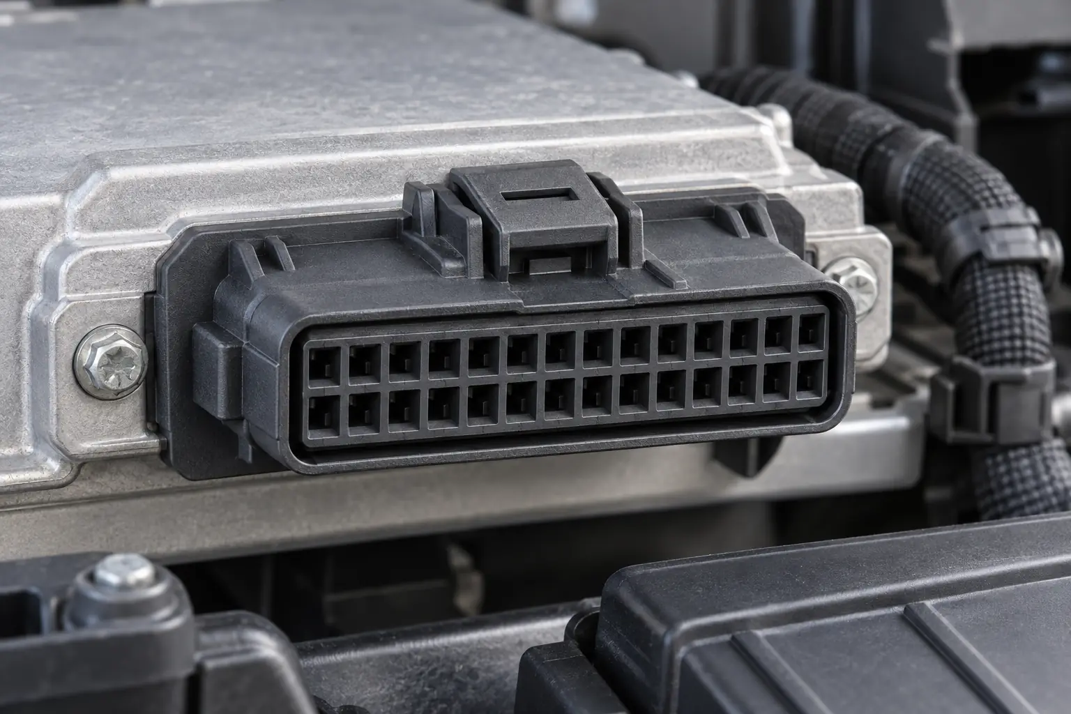
When a harness engineer in Munich received a 26-way connector for a control-module build, she confirmed that the plug latched and released the pilot lot. Assembly errors appeared within the first shift: operators followed a mirrored cavity view and misread the secondary-lock state. The connector was not simply “bad.” The root cause was specification control—the order defined 26 positions, but not the viewing face, cavity map, lock state or complete mating system.
Resumen: Choose a 26 pin automotive connector by its controlled interface, not its cavity count. Freeze the viewing orientation, map all 26 positions, identify both housings and approve the terminal, wire and seal combination. SAE/USCAR-2 and ISO 8092-2 provide automotive test frameworks; IEC 61984 has a different, voltage-defined scope. Require representative samples, lock-state instructions and 100% end-of-line continuity—a latched connector is not necessarily compatible.
Why does a 26-position interface concentrate programme risk?
A 26-position interface can consolidate a body, seat, door, HVAC or instrument module into one serviceable connection. That reduces separate plugs but concentrates risk: one housing may carry power, grounds, outputs, sensor lines and communications only when its contacts and layout are approved for those functions.
“26-pin” states the nominal cavity count, not population, rating, contact size or signal suitability. One programme may reserve four cavities while another uses all 26. Start with a 26-row schedule listing each circuit, wire, terminal, seal, load and routing constraint.
An incomplete schedule creates line containment, repinning, retesting and service ambiguity. Review position-by-position continuity and isolation, then apply the relevant SAE/USCAR-2, ISO 8092-2 or OEM test sequence. Test methods qualify an agreed assembly; they cannot repair an ambiguous drawing.
Why can a 26-position housing have fewer than 26 active circuits?
A position is a moulded cavity; a populated circuit is a cavity fitted with the specified terminal and conductor. Therefore, a 26-position housing may carry 26 circuits, fewer circuits with deliberate reserves, or a combination of active, blocked and sealed vacant positions. Procurement should not convert “26-way” into “26 wires” or assume that every visible cavity accepts a service terminal.
Some connector families are hybrid systems: selected cavities may accept different terminal sizes or contact families for power, low-current signals, grounds or communications. That possibility does not make terminal placement interchangeable. Each cavity must be approved for its assigned contact, conductor cross-section, insulation diameter and, where applicable, individual wire seal. Electrical duty, thermal interaction, creepage or signal-integrity requirements still belong to the vehicle programme and supplier documentation.
The released cavity schedule should record every position as populated, intentionally empty or blocked. For populated positions, record circuit duty, terminal part number, conductor and insulation dimensions, seal or plug requirement, and secondary-lock state. Empty and blocked positions also need explicit plug, sealing and service instructions.
Use this compact evidence checklist before approving a quote or substitution:
- Interface identity: both housing part numbers and revisions, key code, mating-face view and cavity numbering.
- Population evidence: the released 26-position schedule, including intentional vacancies and blocked cavities.
- Component evidence: terminal, wire, insulation, seal or plug and lock-state data for each applicable cavity.
- Verification evidence: approved samples, assembly instructions and tests tied to the actual configuration.
Marketplace labels such as “ECU connector” or “accessory pigtail” describe a possible selling context, not a controlled interface. They do not prove cavity numbering, vehicle pinout, electrical duty, keying, contact plating, seal compatibility or interchangeability; only matched part data and an approved pinout can do that.
How do documented cavity views and lock states prevent assembly errors?
Why must the viewing face be declared before circuits are assigned?
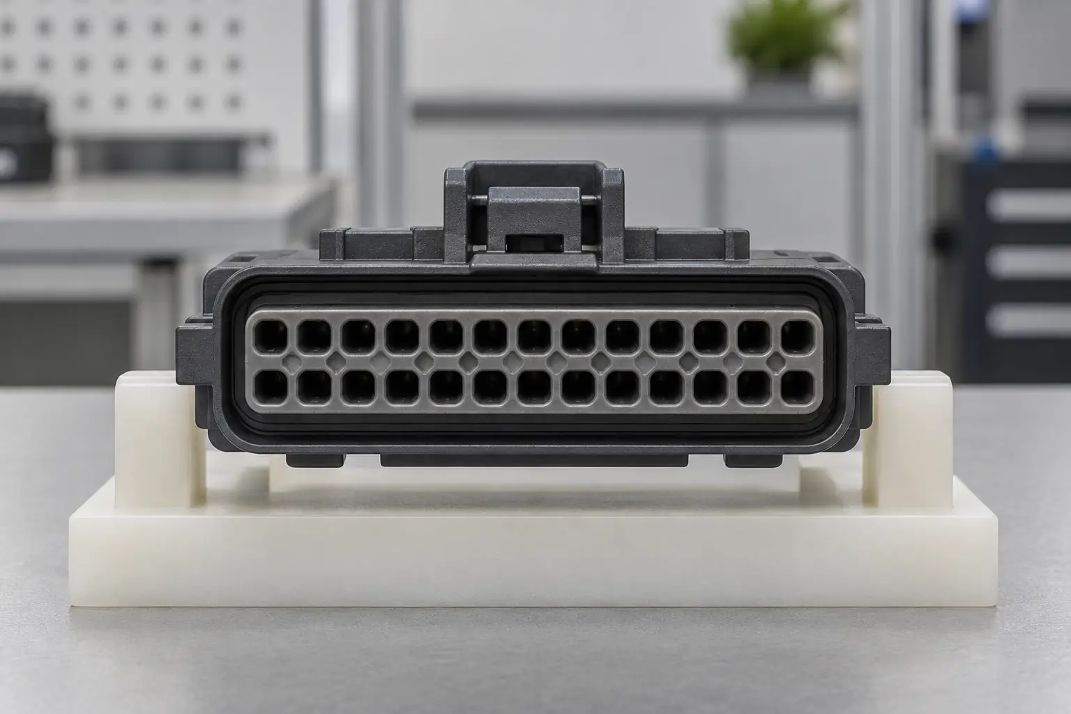
Cavity numbers may appear on the wire-entry side, mating face or drawing. Because opposite views are mirrored, the released drawing needs an orientation cue such as “mating face, latch up,” row labels and a marked cavity 1. A photograph without a stated viewpoint is insufficient.
Reconcile all 26 entries across the schematic, harness drawing, work instruction and test programme. Control blank positions too: specify cavity plugs where sealing requires them, or mark intentional vacancies. Keep the verified map under revision control.
How are terminal retention and connector mating assurance different?
Primary retention holds each terminal in its cavity. A terminal-position assurance device or secondary lock may confirm contact seating; a connector-position assurance feature may secure the mated latch. They perform different jobs, and not every family uses both.
Specify the delivered lock state, insertion sequence, final visual position and service method. A forced lock can hide a partly seated terminal. SAE/USCAR-2 covers connector-system mechanical performance, but insertion, retention and locking limits must come from the product drawing and customer plan.
Why must housings, terminals, wires, seals and locks be approved as one system?
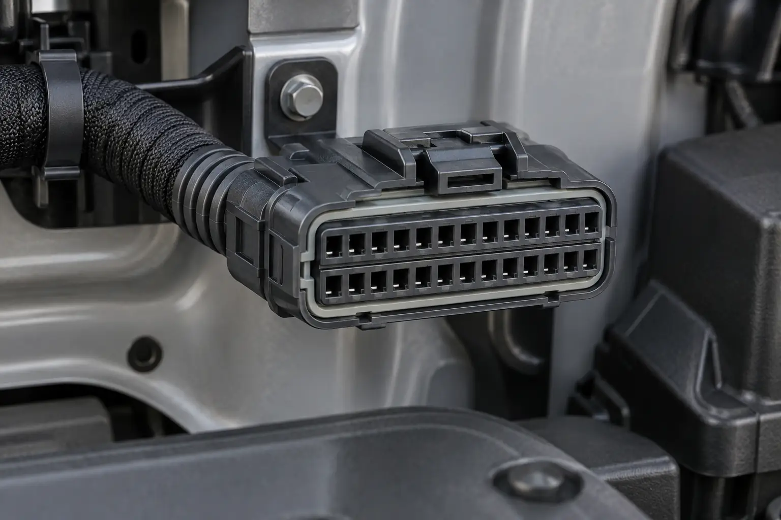
A 26 pin automotive connector combines two housings, compatible terminals and, where required, seals, plugs, locks, strain relief or a lever. Equal cavity counts and an engaged latch do not prove correct keying, contact overlap, seal compression or current paths.
Control both housing numbers and revisions, key code, terminal family and plating, conductor size, insulation diameter and seal range. “Male” and “female” may describe contacts or housings, so part numbers and drawings are safer. Compare keying, cavity pattern and lock geometry with an approved sample; this guide to identifying automotive electrical connectors gives a practical sequence.
Do not infer wire range from cavity count. A family may use one terminal size or several. Approve conductor size, insulation diameter and crimp evidence for every terminal; use this overview of how to crimp automotive connectors as a process checklist, not a substitute for the terminal drawing.
Which sourcing option minimizes total programme risk?
| Decision factor | Undocumented 26-way look-alike | Documented unsealed matched system | Documented sealed matched system |
|---|---|---|---|
| Compatibility evidence | Appearance or hand-fit only | Paired housings, terminals and drawing controlled | Paired parts plus seal and plug system controlled |
| Assembly control | Cavity view and lock state may be unclear | Numbering, keying and lock sequence documented | Same controls plus seal insertion and cavity-plug rules |
| Environmental fit | Unknown | Best for protected, dry locations when validated | Candidate for splash, dust or fluid exposure when validated |
| Unit-cost tendency | Often lowest initial quote | Moderate | Higher due to seals and added assembly steps |
| Repair and maintenance | Tools and replacement contacts may be uncertain | Service parts can be specified | Service parts must also restore sealing |
| Total-cost tendency | High risk of sorting, rework and returns | Usually lower in controlled cabin applications | Usually lower where exposure justifies sealing |
An illustrative total-cost review should include qualification, tooling, assembly, testing, rework and service. If 1% of 10,000 harnesses needed 20 minutes of diagnosis and repinning, the work would consume about 33 labour-hours before line disruption or retest. This is not a defect forecast; it shows why documentation and error-proofing can outweigh a small unit-price difference.
How should installation location change sealing and validation?
| Application zone | Primary concern | Specification priority | Representative evidence |
|---|---|---|---|
| Protected cabin module | Incorrect pinout, fretting or service damage | Keying, strain relief, lock visibility and circuit map | Continuity, contact resistance, vibration and mating-cycle plan |
| Door or seat module | Harness movement and repeated service | Bend control, retention, abrasion protection and access | Harness flex review, mechanical retention and electrical checks |
| Engine-compartment controller | Heat, fluids, vibration and moisture | Validated sealing, temperature class, materials and mounting | Thermal, vibration, fluid and environmental test sequence |
| Exterior or underbody interface | Water, contamination and pressure change | Sealed system, cavity plugs, drainage and service restoration | Application-specific ingress and environmental validation |
“Sealed” is not a complete requirement. Define exposure, temperature, mounting and test conditions. An ingress result belongs to the tested mated assembly with its wires, seals and plugs; do not transfer it automatically to another build.
Which standards can support a 26-position connector validation plan?
- SAE/USCAR-2 is a performance specification for automotive electrical connector systems. Citing it does not prove an unspecified housing, terminal, crimp or harness passed a vehicle programme. State the revision, test category, sample build and limits.
- ISO 8092-2:2023 covers definitions, test methods and general performance requirements for single- and multi-pole road-vehicle harness connections within its voltage-class-A scope. Confirm the edition and customer additions.
- IEC 61984:2008 specifies safety requirements and tests for connectors above 50 V through 1,000 V AC/DC and up to 125 A per contact under stated conditions; it can guide work at or below 50 V. It is not a vehicle-specific blanket certification.
Unsupported compliance claims can trigger a failed audit, rejected approval package or retest. Record the part configuration, wires, seals, tooling, conditioning sequence and results behind each claim.
What evidence should procurement release before the supplier quotes?
- Freeze the interface. Issue both housing numbers, key code, connector-face drawing, mating orientation and revisions.
- Control all 26 positions. List function, wire, terminal, seal or plug, intentional blanks and viewing direction.
- Define assembly. State insertion orientation, initial and final lock positions, crimp tooling and inspection evidence.
- Match validation to the zone. Specify tests, standard edition, customer limits and representative sample build.
- Plan service and traceability. Identify removal tools and repair contacts; retain lot and inspection records.
ZUCH supports interface-based connector sourcing. For a 26 pin automotive connector enquiry, provide the module drawing, cavity schedule, mating details, wire dimensions, installation zone and required evidence—not only a reference photo.
Frequently Asked Questions
What is a 26-pin automotive connector typically used for in high-circuit-count vehicle modules?
It suits modules that need many power, ground, signal or communication circuits through one serviceable interface, such as body, seat, door, HVAC or instrument electronics. Confirm contact layout, current distribution, signal needs and vehicle zone.
How do I confirm that a 26-pin automotive connector matches my vehicle wiring?
Compare housing part numbers, keying, viewing orientation, cavity map, terminals, wire and insulation dimensions, seals and locks. On a representative harness, verify every circuit by continuity, adjacent-circuit isolation and any required loaded voltage-drop or signal test.
Do 26-pin automotive connectors need a matching male and female housing?
Yes. Both sides must be a documented pair with the correct key and mating contacts. Because “male” and “female” may refer to contact or housing, use manufacturer part numbers and interface drawings.
What terminal and wire-gauge options are common for a 26-pin automotive connector?
There is no universal range; it depends on family, cavity, load, conductor and insulation diameter. Some layouts use one terminal size, while others mix sizes. Approve application and crimp data for every populated position.
When should I choose a sealed 26-pin automotive connector?
Choose sealing for exposure to water, dust, road contamination, fluids or condensation when validation requires it. Test the complete mated build with actual wire insulation, seals, cavity plugs and interface seal.
Can I replace one terminal in a 26-pin connector without replacing the full housing?
Often yes, if approved repair parts exist and the cavity, retention, lock and sealing surfaces are sound. Follow the correct process for depinning an automotive connector, install a new crimped terminal, verify retention and lock closure, then repeat continuity, isolation and any loaded check. Replace a cracked, heat-damaged, distorted or non-retaining housing.
Which primary sources define the relevant test scope?
- SAE International, SAE/USCAR-2: Performance Specification for Automotive Electrical Connector Systems
- ISO 8092-2:2023, Road vehicles—Connections for on-board electrical wiring harnesses—Part 2
- IEC 61984:2008, Connectors—Safety requirements and tests
The dependable rule is simple: control the interface on paper before asking the assembly line to control it in plastic and metal.
To review sourcing options, visit the ZUCH product range and contact the team with your drawings, 26-position circuit map, wire data, environmental conditions and validation plan.