Connector Polarization and Keying: Preventing Mis-Mating in Production
Several similar plugs can reach adjacent receptacles in one assembly. A connector may also approach its correct mate upside down, or stop partway while its contacts have already touched. A label cannot physically prevent these conditions, and a latch sound alone does not prove every terminal is seated. The useful question is therefore not whether a housing is described as “error-proof,” but which incorrect attempts its geometry rejects and what evidence confirms full engagement. Connector polarization and keying address different parts of that problem: orientation within an intended pair and exclusion of unintended pairs. Visual coding guides an operator but needs a separate physical control where wrong pairing has to be blocked.
The short answer: Specify polarization for the permitted mating orientation, assign distinct compatible key options across look-alike interfaces, and test every prohibited plug-to-receptacle pairing on representative hardware. Check not only whether a wrong pair reaches its final latch position, but whether it can make partial electrical contact first. Verify intended mating, terminal seating and any latch or assurance device against the actual product specification. These measures reduce defined assembly risks; they do not establish universal error-proofing, electrical suitability or approval of a particular model. Harwin’s What are Polarization and Keying in Connectors? (19 August 2020) distinguishes the two geometric functions, while Molex’s connector-mating guide separates them from visual coding.
Contents
Why does mis-mating happen in production?
Similar housings close together invite a neighbour swap if their mating faces accept the same plug. A symmetric interface can permit reversed insertion even when the correct pair is selected. Restricted visibility makes markings less useful. Partial mating is a different failure: the intended halves may align correctly but fail to reach their specified seated state. These are design scenarios to assess, not measured incident rates. Harwin explains the first two geometric distinctions; Molex’s connector-mating guide also distinguishes mechanical attributes from identification cues.
| Mis-mating scenario |
Enabling condition |
Geometric control |
| Reversed insertion |
Symmetric interface |
Polarization feature in both halves |
| Neighbour swap |
Identical housings adjacent |
Distinct key options per pairing |
| Partial mating |
No engagement feedback |
Latch with tactile or audible cue |
The final row is only a detection aid: a cue must be correlated with the manufacturer’s seated-position criteria, and a partly inserted wrong pair must not be assumed electrically open merely because the latch has not closed.
What is the difference between polarization, keying and visual coding?
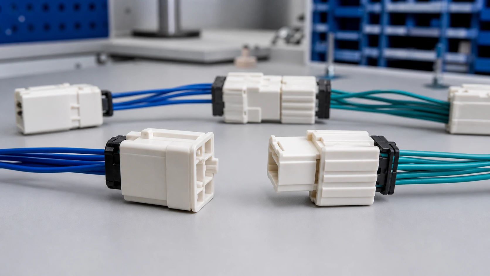
Connector polarization and keying answer two separate questions. Polarization constrains the orientation of two halves that are meant to mate, such as rejecting a 180-degree reversal. Keying distinguishes otherwise similar intended pairings, so a plug assigned to position A should not mate with position B. A rib, slot, asymmetric shroud or inserted key can perform either role according to its arrangement; the name of the feature does not prove the resulting pair matrix. Harwin explicitly notes that one feature may serve both functions. Color and labels are visual coding: they communicate identity to an operator, but color alone does not block an incorrect physical connection. Molex distinguishes visual coding from mechanical variants that actually prevent mating.
How should key options be assigned across similar connectors?
Map every interface in the assembly that shares a family or size, then assign distinct key options, and add colour as a secondary human cue. Keep a keying chart in the drawing set so future variants extend the scheme instead of colliding with it. Include service connectors and alternate harnesses that could be present in the same work area, not just adjacent positions in one build. Check the actual mating-part numbers on both sides: two differently named key options are useful only if intended pairs fit and every prohibited pair is rejected under the defined assembly conditions.
A simple assignment register can use rows for plug IDs and columns for receptacle IDs. Mark intended intersections as “mate” and every other reachable intersection as “prohibited.” Record key codes, pin assignments and the revision of each physical sample alongside the chart. This is a project control, not a generic manufacturer compatibility claim.

Which housing and terminal features address different failure modes?
Asymmetric shrouds, ribs, slots and coded inserts do the geometric work. A connector latch retains mated halves and may provide tactile or audible feedback, but that is not a substitute for proving wrong-pair exclusion or contact engagement. A terminal lance retains an individual contact in its cavity; a family-specific terminal-position assurance (TPA) feature can add a secondary terminal-level control. Connector-position assurance (CPA), where specified, acts at the mated connector interface. Molex’s contact-retention discussion separates these layers and notes family-dependent implementations. For a related technical reference, see Connector Housing Selection: Material, Keying and Retention Features.
| Verification step |
Method |
Record |
| Wrong-pair rejection |
Attempt matrix on real hardware |
Trial matrix with results |
| Orientation control |
Installed-view inspection |
Drawing sign-off |
| Variant protection |
Keying chart review at change |
Updated chart revision |
For each step, define acceptance in the applicable product drawing or detail specification. IEC 60512-1:2018 is a generic testing specification; it does not itself assign test severities, permissible performance limits or certification to this connector. Those decisions belong in the product-specific validation plan.
How should keying be captured in drawings and instructions?
Call out the key option code on each half, show the orientation in the installed view, and reference the keying chart from both drawings. Work instructions should present the connector as seen by the operator, with the key feature visible in the image. Identify the cable-side and equipment-side part numbers, cavity or pin-one reference, and any separate coding color. A drawing revision that changes a key assignment should trigger a review of the prohibited-pair matrix, stocked variants and service replacements.
Important: General guidance cannot approve a specific design or lot. Apply the mating and retention principles through controlled drawings, the supplier’s applicable specifications and an acceptance plan. A visual color match, latch click or TPA position must not be treated as proof of all electrical and mechanical conditions. For a related technical reference, see Energy Storage Connector Anti-Mis-Mating Design for Battery Racks.
How should prohibited pairings and partial engagement be verified?
Attempt the wrong connections deliberately on representative hardware and confirm each one is physically rejected. Record the trial matrix with the build documentation, and repeat it whenever a variant, supplier change or new key option enters the system. Test intended pairs in their allowed orientation, then try each prohibited plug against each reachable receptacle in plausible orientations, including the position at which a wrong pair first meets resistance. Do not force parts beyond the controlled assembly procedure or damage samples and infer production behavior from them.
For a prohibited pair, record separately whether the housing starts to enter, whether contacts touch or a circuit can become energized before mechanical stop, and whether a latch can engage. A wrong pair that cannot fully latch may still be unacceptable if partial electrical engagement is possible. For the intended pair, verify seated depth and lock state using its product-specific criteria; inspect terminal position and the required TPA or CPA state separately where those devices exist. Agree the safe test state and method with the responsible electrical engineer before continuity checks. IEC 60512-1:2018 provides a framework for prescribed connector tests, not a universal pass/fail threshold for these attempts.
What should accompany a ZUCH housing inquiry?
Use ZUCH’s Plug Housing category and the live product catalogue to identify relevant connector, terminal or housing component families. These are discovery routes only and do not demonstrate that a specific configuration is approved for your application.
What belongs in the RFQ?
- Interface list with families, sizes and adjacency in the build, including accessible service and variant interfaces.
- Key option assignments on both halves, visual colours and the controlled keying chart reference.
- Latch feedback, seated-position criteria and any terminal-position or connector-position assurance requirements.
- Prohibited-pair trial matrix, partial-contact concern, sample revisions and required acceptance records.
What remains a project-specific fit decision?
This guide supports engineering and sourcing discussion; it cannot replace programme-specific validation, market requirements, or an approval record. Use ZUCH’s sample request route or contact page for controlled component documentation and samples.

FAQ
What is connector polarization?
Geometry that constrains the orientation between matching halves, typically rejecting reversed or offset insertion. Check the actual keyed mating pair and pin assignment; the term alone does not demonstrate every wrong orientation is harmless.
What is connector keying?
Assigned mechanical differences intended to distinguish similar plug-to-receptacle pairings. Confirm the allowed and prohibited pairings with both halves’ actual part numbers and physical samples.
Why not rely on labels and operator training alone?
Labels and colors guide identification but do not necessarily stop the wrong connector entering. Use mechanical exclusion when the risk assessment requires it, while keeping labels as helpful inspection and service cues.
How are key options assigned in a multi-connector product?
List all similar reachable interfaces, assign the intended pairings, then document which cross-pairings must fail. Include variants and service parts in the matrix before releasing the chart.
What confirms that mating is complete?
Use the product-specific seated-position and latch criteria, not a click alone. Where fitted, inspect terminal seating and TPA separately from the housing latch or CPA; each protects a different interface.
How is mis-mating prevention verified?
Attempt every prohibited pairing on representative, revision-controlled hardware and record insertion, partial contact and latch outcomes separately. Verify the intended pairs still seat correctly, and repeat the matrix when a relevant component changes.
What keying details belong in an RFQ?
Provide the interface map, mating part numbers, key assignments, colors, pin mapping, engagement criteria and prohibited-pair matrix. Ask for matching drawings and samples rather than assuming a catalog family name guarantees compatibility.
References
How should the final connector assignment be approved?
Connector polarization and keying should be specified as two testable controls, not one blanket promise: first establish the intended orientation, then assign the permitted pairings and prohibit the rest. Visual color and labels can make those assignments easier to recognize, but they cannot substitute for a mechanical barrier where the wrong connection matters. Approve the scheme only after the actual part numbers, harness variants and installation views are reconciled with a prohibited-pair matrix. Check for partial electrical contact before a mechanical stop as well as full seating, latch state and terminal retention on intended pairs; use the relevant product specification for acceptance. The public manufacturer explanations and generic IEC test framework do not validate a ZUCH configuration. For a specific build, request controlled drawings and samples through ZUCH’s existing product and contact routes, then record the project’s own verification results.
 Zhejiang ZUCH Technology Co., Ltd.