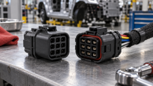
Connector Polarization and Keying: Preventing Mis-Mating in Production
Mis-mating is prevented by geometry that makes the wrong connection physically impossible, assigned deliberately across every similar interface in the build. Design the assignment; do not rely on operator attention.
Contents
Part 1. Why does mis-mating happen in production?
Errors cluster where similar housings sit close together, where a connector can physically enter the wrong counterpart, or where a symmetric shape allows reversed insertion. Fatigue, line speed and blind access amplify whatever geometry permits.
| Mis-mating scenario |
Enabling condition |
Geometric control |
| Reversed insertion |
Symmetric interface |
Polarization feature in both halves |
| Neighbour swap |
Identical housings adjacent |
Distinct key options per pairing |
| Partial mating |
No engagement feedback |
Latch with tactile or audible cue |
Part 2. What is the difference between polarization and keying?
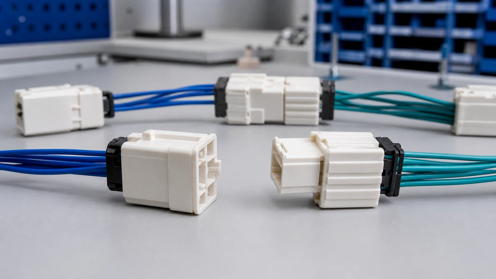
Polarization guarantees a single orientation between two halves that belong together, blocking reversed or offset mating. Keying distinguishes between different pairings, so a plug fits its own receptacle and physically rejects the neighbouring one.
Part 3. How should key options be assigned across similar connectors?
Map every interface in the assembly that shares a family or size, then assign distinct key options, and add colour as a secondary human cue. Keep a keying chart in the drawing set so future variants extend the scheme instead of colliding with it.

Part 4. Which housing and terminal features support error-proofing?
Asymmetric shrouds, ribs, slots and coded inserts do the geometric work, while latches confirm completed mating with a tactile or audible cue. Terminal-position assurance features add a second layer by rejecting incompletely built connectors before they reach the line. For a related technical reference, see Connector Housing Selection: Material, Keying and Retention Features.
| Verification step |
Method |
Record |
| Wrong-pair rejection |
Attempt matrix on real hardware |
Trial matrix with results |
| Orientation control |
Installed-view inspection |
Drawing sign-off |
| Variant protection |
Keying chart review at change |
Updated chart revision |
Part 5. How should keying be captured in drawings and instructions?
Call out the key option code on each half, show the orientation in the installed view, and reference the keying chart from both drawings. Work instructions should present the connector as seen by the operator, with the key feature visible in the image.
Important: General guidance cannot approve a specific design or lot. This is a source-note application of the IPC and TE Connectivity references listed below; apply it through your controlled drawing and acceptance plan. For a related technical reference, see Energy Storage Connector Anti-Mis-Mating Design for Battery Racks.
Part 6. How should error-proofing be verified before ramp?
Attempt the wrong connections deliberately on representative hardware and confirm each one is physically rejected. Record the trial matrix with the build documentation, and repeat it whenever a variant, supplier change or new key option enters the system.
Part 7. Which ZUCH route supports an error-proofing inquiry?
Use ZUCH’s Plug Housing category and the live product catalogue to identify relevant connector, terminal or housing component families. These are discovery routes only and do not demonstrate that a specific configuration is approved for your application.
RFQ inputs
- Interface list with families, sizes and adjacency in the build.
- Key option assignments, colours and the keying chart reference.
- Latch feedback and terminal-position assurance requirements.
- Wrong-pair trial matrix, samples and acceptance records.
Fit Boundary
This guide supports engineering and sourcing discussion; it cannot replace programme-specific validation, market requirements, or an approval record. Use ZUCH’s sample request route or contact page for controlled component documentation and samples.

FAQ
What is connector polarization?
Geometry that allows only one orientation between two matching halves, preventing reversed or offset mating.
What is connector keying?
Assigned geometric codes that let each plug fit only its intended receptacle among similar connectors.
Why not rely on labels and operator training alone?
Labels guide attention but do not stop insertion; geometry rejects the wrong connection even on a fast or blind assembly step.
How are key options assigned in a multi-connector product?
Map all similar interfaces, give each pairing a distinct key option, add colour cues, and maintain a keying chart in the drawing set.
What confirms that mating is complete?
A latch with tactile or audible feedback, checked in process, and where used, terminal-position assurance features.
How is mis-mating prevention verified?
By deliberately attempting wrong connections on representative hardware and recording that each attempt is physically rejected.
What keying details belong in an RFQ?
The interface map, key assignments, colours, latch feedback expectations, trial matrix and required records.
References
 Zhejiang ZUCH Technology Co., Ltd.