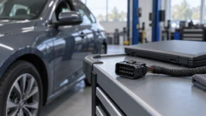
Aumento de temperatura del conector del motor: revisar las entradas de los terminales y la carcasa
Aumento de temperatura del conector del motor: revisar las entradas de los terminales y la carcasa
A motor connector’s catalog current can look sufficient while leaving an important question unanswered: does that value cover the actual terminal, wire, housing, surrounding heat, and motor duty? A short starting event and sustained operation expose the connection to different thermal conditions, and changing the harness or loading adjacent contacts can make an earlier comparison incomplete. Selecting only by the housing outline leaves procurement without a clear basis for accepting a sample or approving an alternate. This guide explains how to define the thermal question, review the conductive path and enclosure inputs, request a useful test record, and apply derating evidence without turning one configuration’s results into a universal rating.
The short answer is to select the complete connection, not an isolated terminal. Identify the mated parts, conductor and termination, then separate starting duty from continuous current and define the local ambient and adjacent-circuit loading. IEC 60512-5-2:2002 describes a current-temperature derating test at elevated ambient temperature; it does not assign every motor connector the same allowable current. For a new design or replacement, request evidence for the intended arrangement and compare it with documented component limits. A housing image or a room-temperature sample observation cannot establish acceptance for a hotter, differently populated installation.
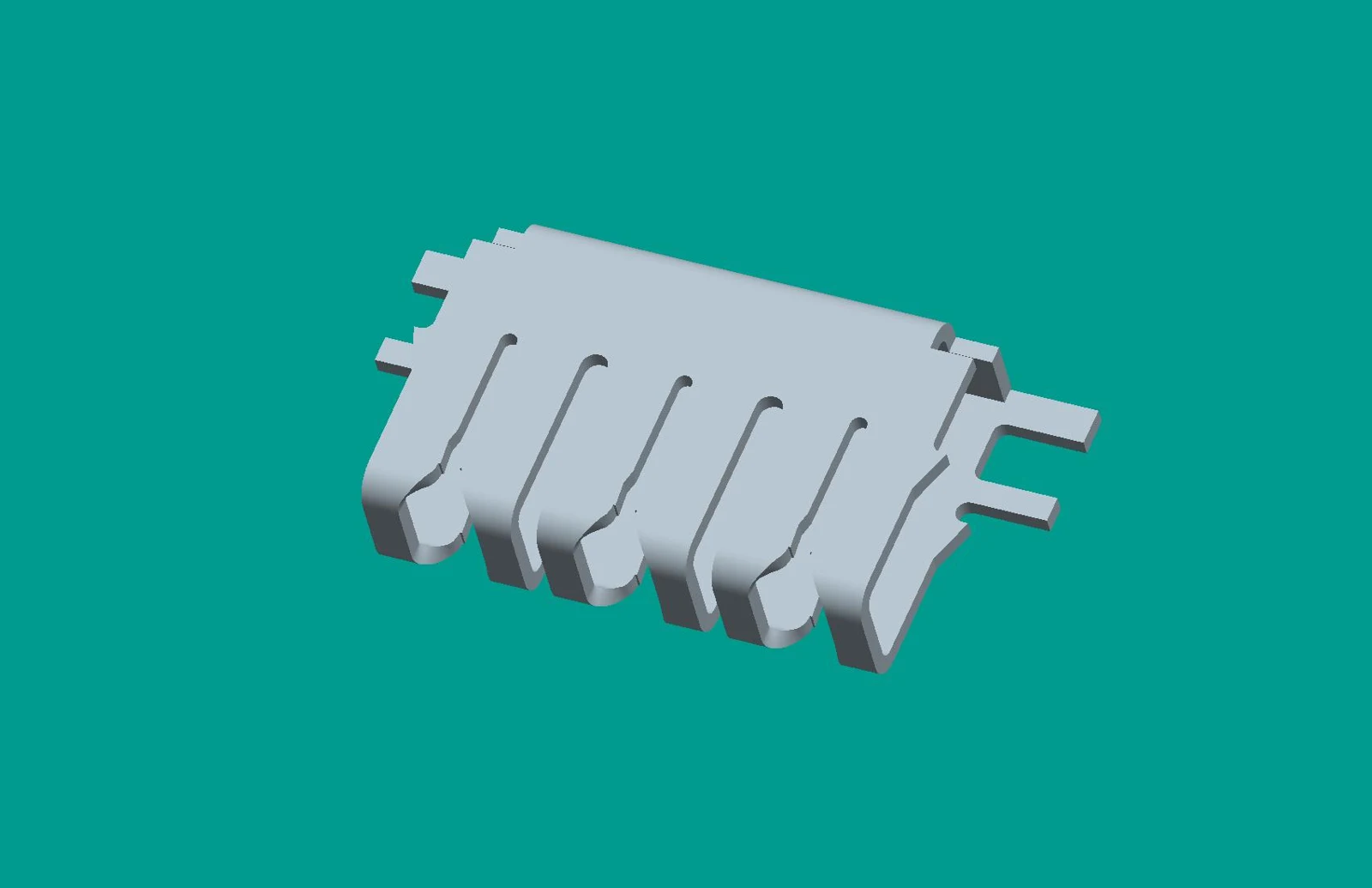 For a related technical reference, see Durabilidad del conector del compresor: revisión de las entradas de arranque-parada y desgaste por contacto.
Contents
What thermal question must the selection answer?
State whether the buyer is assessing a released connection, a new sample, or an alternate. The decision might be whether a documented configuration can carry the expected continuous load, whether repeated starts need separate evaluation, or whether a replacement remains within an existing qualification boundary. Those are different questions; a bare request for a “high-current motor connector” does not define any of them.
Temperature rise is the increase at a specified measurement point relative to the recorded ambient. Absolute temperature and temperature rise must be distinguished: the same rise at a higher ambient leaves a different absolute temperature at the component. Request both the measurement location and the ambient reference rather than comparing unlabeled temperature figures. The relevant limits must come from the controlled component and application specifications, not a generic limit supplied by this article.
Why does contact resistance matter?
The basic resistive-loss relationship is P = I²R: current through a resistance dissipates electrical power as heat. The conductive path includes the conductor termination, terminal body, and mating contact interface. A localized resistance increase can therefore become a localized heat source, while current also affects heating along the wire. This relationship explains why thermal selection must address the finished connection rather than only the nominal metal size.
The equation alone does not predict temperature rise. Heat transfer, geometry, contact condition, time, and the surrounding arrangement also matter, and resistance need not remain constant throughout operation. A warm connection is not by itself proof of a defective terminal; equally, a continuity check is not a thermal-capacity result. Define the tests and acceptance criteria in the detail specification. IEC 60512-1:2018 identifies preparation, tests and measurements, requirements, and documentation as part of the connector-evaluation framework.
Record the connector, mating part, terminal population, housing, keying, and revision. Add the conductor specification and approved termination process. A similar housing image cannot substitute for controlled drawings, and an alternate terminal that enters the cavity is not automatically equivalent in contact geometry, material, plating, retention, or wire compatibility.
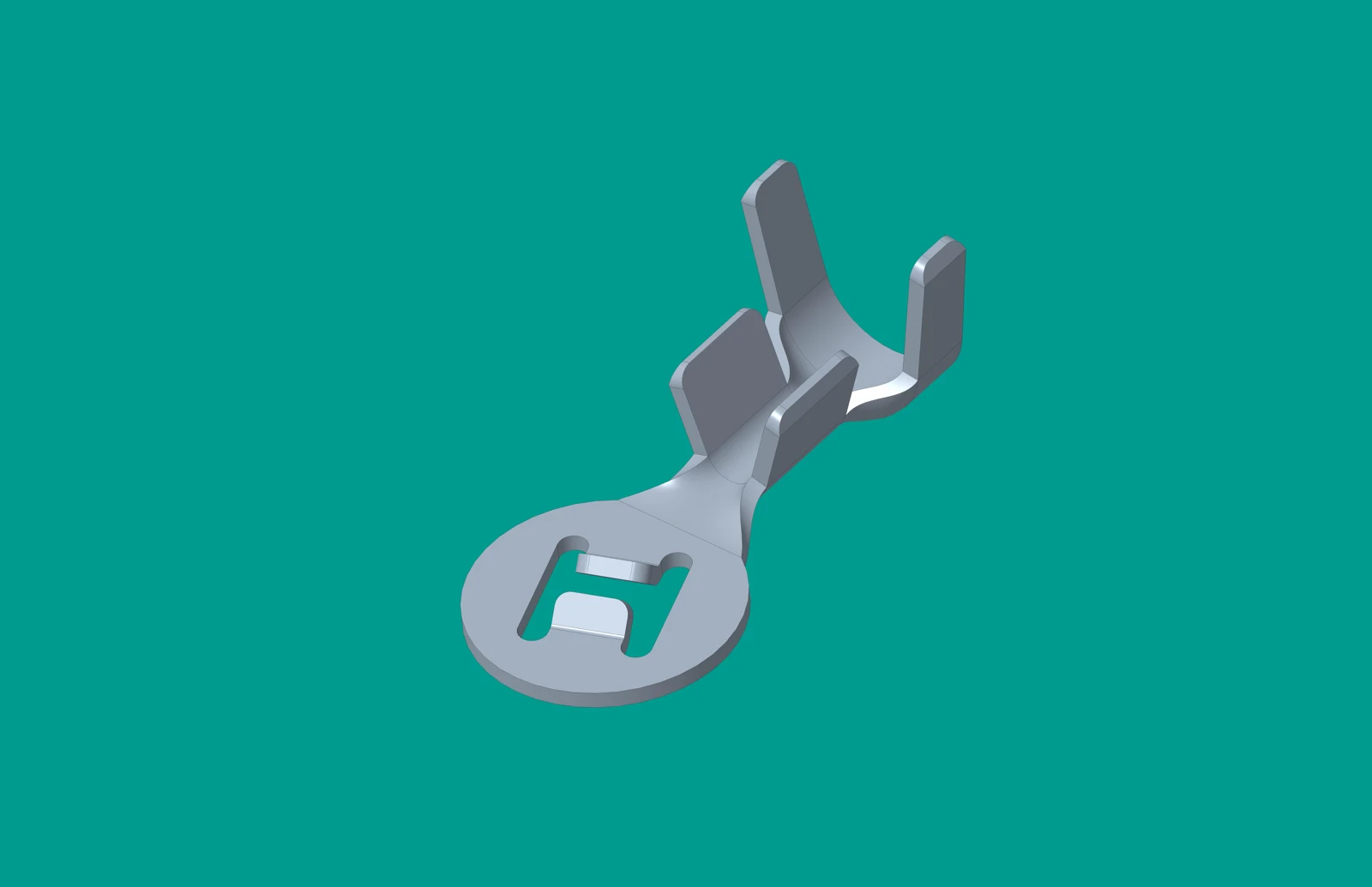
For the terminal, request the specified mating interface, conductive material, finish, wire range, and assembly instructions. For the wire, record cross-section, construction, insulation specification, preparation, routing, and support. A different wire or termination can alter both the electrical path and the thermal arrangement. Do not enlarge the conductor as an improvised fix if that wire is outside the terminal’s released range; the resulting termination needs its own compatibility and process review.
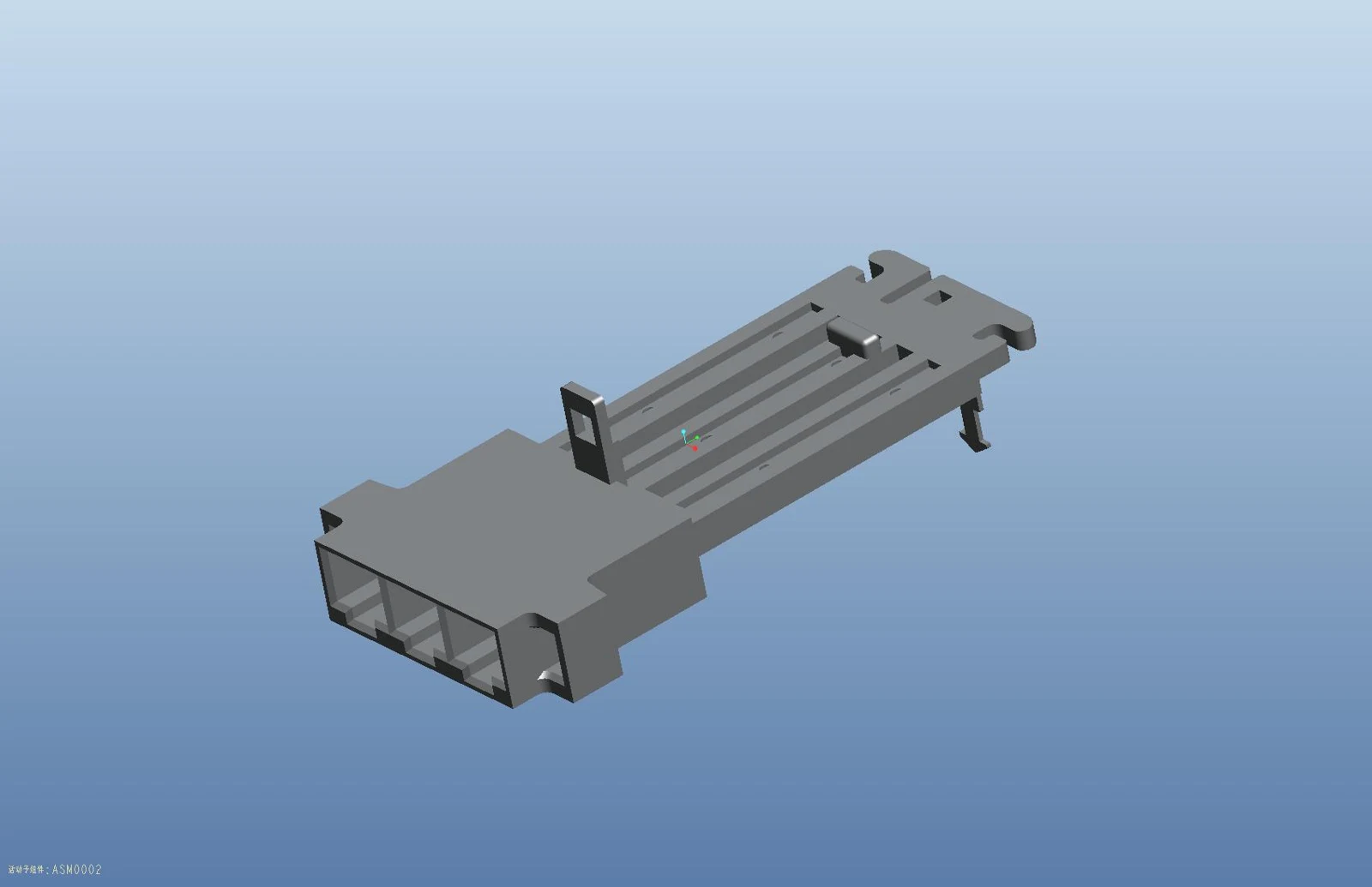
For the housing, confirm the actual material grade and applicable temperature limits, not only a family name such as nylon. Review cavity population, retention, nearby surfaces, enclosure space, and ventilation as configuration inputs. These are review questions rather than proof that a particular geometry will run cooler. Housing material, terminal, and wire limits must be considered together; one component’s limit does not cancel another’s.
Important: Do not infer a current or temperature rating from a product image or visible terminal feature. A thermal result also does not establish insulation coordination. IEC 60664-1:2020+AMD1:2025 addresses clearances, creepage distances, and solid insulation within its stated low-voltage equipment scope; relevant application requirements must be reviewed separately.
Which current and installation conditions need to be recorded?
Keep the stated current, ambient boundary, duty context, conductor arrangement, routing, and support conditions with the inquiry. These inputs explain what evidence a project must request. Use the motor and control-system documentation to establish the load profile; do not substitute an assumed starting-current multiplier for the intended motor, drive, and operating mode.
How should starting current and continuous current be separated?
Describe continuous operation with its current and duration. Describe starting events with their current profile, event length, repetition, and recovery interval. If overload or stalled operation is part of the equipment’s approved validation plan, identify that condition separately and include the protection behavior. The highest instantaneous current is not enough to describe cumulative heating, and a continuous-current evaluation does not automatically qualify every repeated-start pattern.
Where current varies, ask the responsible engineer to define the waveform or equivalent load used for thermal assessment. For a purely resistive path with constant resistance, RMS current relates to average resistive heating, but that simplification does not establish the peak temperature of a changing, thermally coupled connection. The test record should show which operating condition it represents.
Why do local ambient and adjacent circuits matter?
The connector’s local environment may differ from the room outside the equipment. Record nearby motor or electronic heat sources, enclosure conditions, air movement, cable bundling, and the loaded cavities. Adjacent current-carrying contacts may contribute heat to the same assembly, so evidence for a lightly populated connector should not be assumed to cover a fully loaded one. Request the tested loading pattern rather than interpreting pin count as current capacity.
IEC 60512-5-2:2002, Test 5b specifically addresses current-carrying capacity at elevated ambient temperature. That scope supports requesting ambient-dependent evidence, not declaring a universal derating percentage. Keep the installation description with the report so its applicability can be checked when packaging or harness routing changes.
What evidence supports temperature-rise acceptance and derating?
Ask which configuration an evaluation covers and what conditions were recorded. A sample observation should not become a universal rating for an unlisted terminal, housing, or harness. Under IEC 60512-1:2018, detail product specifications prescribe the tests, severity, and permissible performance limits. Merely citing the IEC 60512 series leaves those decisive details unresolved.
| Review question |
Evidence to request |
Decision boundary |
| Does the sample match the proposed assembly? |
Part revisions, mating parts, terminal population, wire and termination records |
Resolve unmatched parts before transferring results |
| Does the load cover the intended duty? |
Applied current profile, duration, repetition and loaded cavities |
Do not equate one steady load with every start pattern |
| Can the temperatures be interpreted? |
Local ambient, sensor locations, time history and stabilization criterion |
Separate absolute temperature from rise at each point |
| Does elevated-ambient evidence apply? |
Derating data with configuration, method and applicable temperature limits |
Use only the documented range and conditions |
| What establishes acceptance? |
Agreed detail specification, test edition, limits and disposition |
A named method is not product certification |
A useful thermal record links sample identification to the setup, instruments, calibration information, measurement positions, ambient, electrical loading, and results over time. It also records the agreed endpoint or stabilization criterion, preconditioning where specified, deviations, acceptance limits, and the review disposition. This is a practical request checklist, not a claim that every item is a mandatory clause in the publicly described standard. A single unlocated photograph of a temperature display is not a substitute for that record.
How should a derating curve be used?
First confirm which terminal, conductor, housing, population, and installation the curve represents. Then compare the intended local ambient and current with the documented range, while checking applicable terminal, housing, and wire temperature limits. Ask how any design margin is defined. Do not invent a percentage, extrapolate beyond the stated range, or combine one terminal’s curve with a different housing to create an undocumented assembly rating.
The public description of IEC 60512-5-2 establishes its elevated-ambient test purpose, but provides neither this article’s component limits nor a ZUCH-specific curve. If the proposed application is outside the supplied evidence, the next step is a documented gap review and an agreed evaluation, not an unqualified approval. This also avoids quoting an unnecessarily different terminal before finding that the original problem was an unsupported test-to-application comparison.
What should a motor-connector thermal RFQ include?
Use the following RFQ fields to align engineering and procurement before comparing quotations. Add the current profile, local ambient, loaded-cavity map, and requested test-record fields to the relevant rows. A supplier can then distinguish a drawing clarification from a sample request or a validation gap, instead of replying with an isolated catalog ampere value.
| RFQ field |
Provide |
Purpose |
| Connection |
Drawings, mating part, terminal, housing, revision |
Identify the configuration |
| Thermal boundary |
Current, ambient, duty, harness arrangement |
Define the question |
| Evidence request |
Sample objective, records, open questions |
Make review traceable |
| Change control |
Alternate and revision expectations |
Prevent silent scope expansion |
State the required assembly-document revision and inspection basis as well. The public IPC Standards Revision Table lists IPC/WHMA-A-620, Requirements and Acceptability of Electronic Wire Harnesses and Cables. It can help identify the document and revision for discussion, but the listing does not provide crimp dimensions, workmanship limits, or a thermal rating. Request the controlled requirements actually used by the program rather than claiming compliance from the listing alone.
When does a change require another review?
A changed terminal, housing, wire, route, current condition, or requirement can invalidate an earlier comparison. Compare the proposed change with the report’s configuration and operating boundary, document what remains covered, and identify the evidence gaps before releasing an alternate. A cosmetic-looking change should not be dismissed without checking the controlled drawing and material specification.
Thermal and mechanical reviews answer different questions. See the vibration-retention checklist for a separate evidence lens; a satisfactory temperature result cannot replace retention verification. Keep the approved drawing, harness process, loading map, and acceptance record linked so subsequent production or service changes can be assessed against the same baseline.
FAQ
Is temperature rise a connector-only property?
No. It belongs to the complete connection and its operating conditions, including the wire, termination, loaded contacts, and local environment. Before using a reported result, confirm the measurement point and the configuration it covers.
Identify the connector, mating part, terminal, housing, revisions, conductor, and termination process. Then define continuous and starting duty, local ambient, and harness arrangement. A current figure without those inputs leaves the acceptance boundary unclear.
Can a housing image prove a rating?
No. Appearance does not establish material grade, terminal compatibility, operating limits, or test results. Use the image for identification only, then confirm the drawing and configuration-specific evidence.
Why record the harness arrangement?
Wire selection, bundling, routing, support, and adjacent heat sources define the application being assessed. Recording them lets a reviewer check whether a test setup is relevant and whether a later change needs additional evidence. It does not imply a quantified benefit from any particular routing change.
When should a comparison be repeated?
Review it after a configuration, condition, requirement, or evidence-scope change. The review determines whether the existing results remain applicable or additional testing is necessary; every change need not trigger an identical test program. Keep that disposition traceable.
What belongs in the RFQ?
Send drawings and revisions, the current and ambient boundary, harness arrangement, sample objective, requested evidence, and change expectations. Include the loaded-cavity pattern and agreed acceptance basis so suppliers can respond to the actual assembly. Mark unknown inputs for engineering resolution rather than inventing them.
Does a continuous-current rating cover motor starting?
Not automatically. Starting-event magnitude, duration, repetition, and recovery need to be compared with the supplied evidence and intended protection behavior. A short peak is neither proof of failure nor proof of suitability without that duty context.
Can the same derating curve be used for a different wire or terminal?
Only if the evidence explicitly covers that configuration or a documented engineering review establishes its applicability. IEC 60512-5-2 describes a test method, not permission to transfer results between unspecified assemblies. Ask for configuration coverage before applying the curve.
References
Conclusion
Motor connector temperature rise is a configuration-and-duty question, not a number that belongs to the housing alone. Begin with the controlled mating parts, terminal, conductor, and termination process; then define continuous load, starting events, local ambient, and adjacent-circuit loading. Compare those inputs with a traceable thermal record and any applicable derating data before accepting a sample or alternate. Do not transfer a result to an untested arrangement merely because the parts look similar, and keep insulation and retention verification separate from thermal acceptance. The ZUCH motor connectors route provides a product-family starting point. Send the defined configuration and evidence questions through the sample request route so the inquiry remains tied to the intended assembly and its verification boundary.
 Zhejiang ZUCH Technology Co., Ltd.