Female Terminal Contact Retention: Causes of Back-Out and How to Prevent It
A harness can pass a continuity check at the bench yet develop an intermittent circuit after the connector is mated or the wires are dressed. If a female contact shifts rearward in its cavity, the first question is whether its primary retention feature ever engaged, not whether the wire still conducts. A rearward contact may lose mating engagement without a broken crimp; a conductor pulling out of the crimp is a different failure. Either can trigger rework, investigation, or an unreliable release if the two are confused. This guide separates those paths, explains the role of secondary retention, and sets out the drawing-controlled checks needed before accepting or repairing the assembly.
The short answer: Female terminal contact retention is the ability of a contact to stay at its specified position in a matched housing under defined assembly and application loads. Prevent back-out by confirming the terminal/housing pairing and orientation, full primary-lance engagement, the specified secondary feature where fitted, and wire routing that does not pull on the contact. Continuity alone does not prove any of these mechanical conditions. IEC 60512-1:2018 provides a generic connector test framework, but the detail product specification must select the tests, severity, and permissible limits; there is no universal pass force for every female terminal. Inspect the actual cavity and controlled drawing, then use that connector system’s documented retention method and acceptance criteria.
Contents
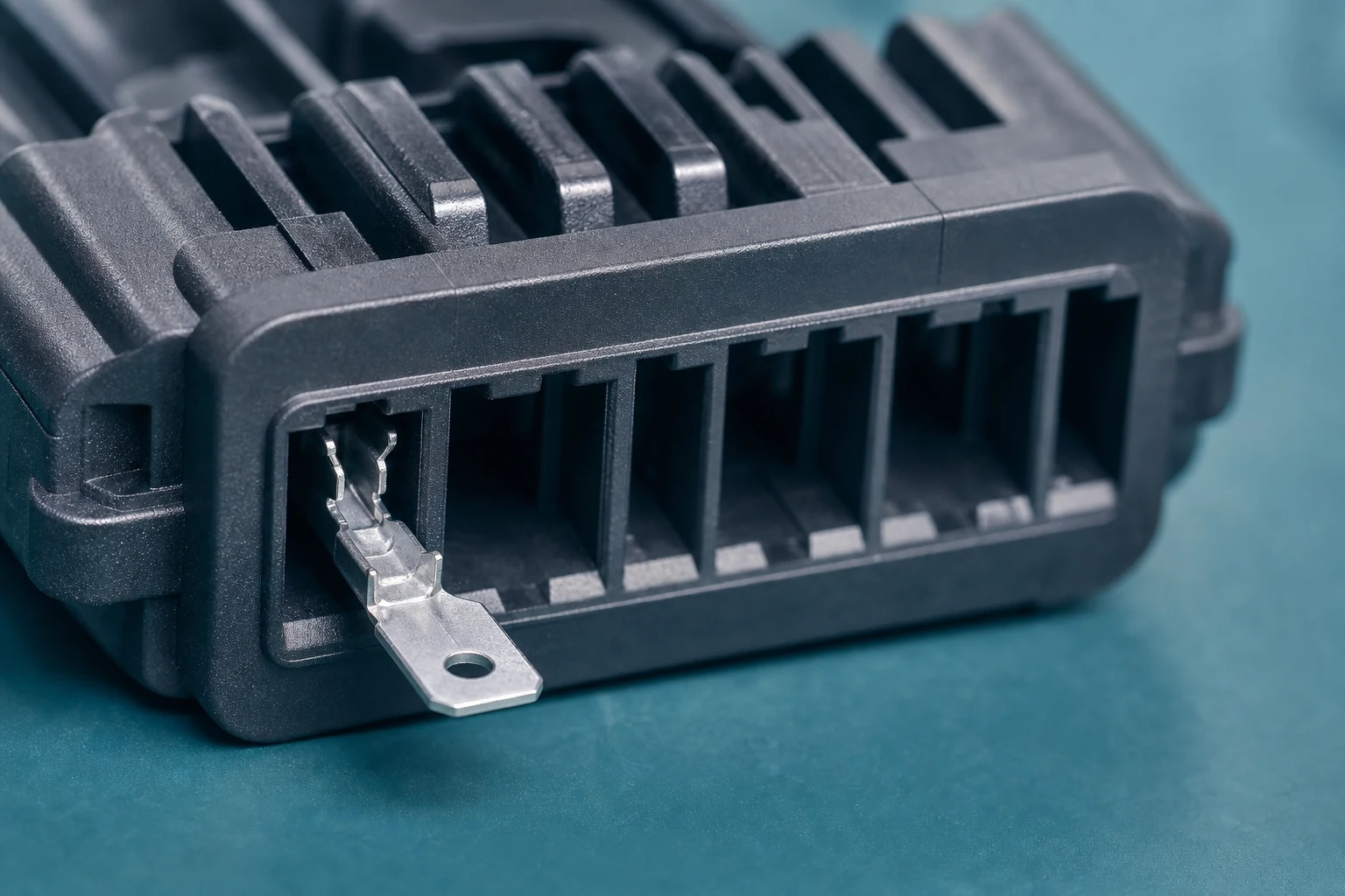
Stable retention depends on a female terminal remaining in its intended housing position after insertion and during the specified handling or service conditions. The outcome involves the contact, cavity geometry, primary lance, insertion path, wire dress, secondary retention where used, and the programme acceptance plan. The housing-to-housing latch is a separate interface: it may hold the connector halves together while one contact has moved inside its cavity.
A good electrical reading establishes continuity at the instant and configuration tested. It does not establish correct seating depth or resistance to later wire load. Conversely, a properly retained contact still needs separate crimp and mating-interface verification. The distinction matters when a technician traces an intermittent circuit: check the contact position before assuming the conductor-to-barrel joint failed.
| Retention review |
What to confirm |
Programme impact |
| Cavity match |
Does the contact family match the housing cavity and orientation? |
A wrong pairing can prevent the intended lock from engaging |
| Lance engagement |
Is the primary lance fully engaged with the housing feature? |
Partial engagement can look seated while still allowing movement |
| Post-insertion loads |
What wire routing, seal, or bundle forces act on the contact after assembly? |
External loads can challenge an otherwise correct insertion |
Where does back-out begin, and how is it different from crimp failure?
Back-out can begin when the terminal is not fully inserted, when a lance has been damaged or has not engaged its housing feature, or when the contact and cavity are not the intended pair. A terminal that appears present at the rear of a connector may still be short of its intended locked position. Visual cues must be tied to the controlled design rather than informal assembly habits. Molex’s contact-retention guidance identifies incomplete engagement, deformation, cable strain, and vibration as relevant mechanisms; those are diagnostic possibilities, not proof of the cause in a particular harness.
Separate the physical evidence before selecting a remedy. If the entire terminal moves backward relative to the housing while the wire remains crimped to it, investigate the contact-to-cavity retention path. If the wire moves out of a terminal that remains seated, investigate the crimp, wire preparation, tooling, and applicable crimp acceptance criteria. If both move, preserve the assembly and assess both interfaces. A continuity check or a pull on the wire alone may not isolate which interface yielded.
How do the primary lance and housing feature hold the contact?
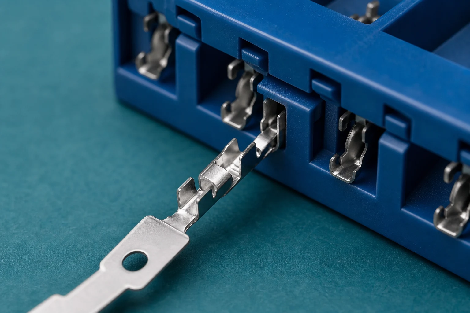
A primary lance normally engages a defined feature in the housing to resist rearward movement. The engagement depends on the terminal orientation, the shape and condition of the lance, the cavity feature, and insertion depth. Some systems use a contact lance; others use a housing lance, so locate the actual retention feature on the approved drawing instead of assuming every design has the same window. Treat the terminal and housing as a matched interface; a general terminal family name does not prove compatibility. For a related service reference, see How to Depin Automotive Connector?.
The insertion check should compare the contact’s specified datum or rear-face position to the controlled drawing and any approved visual, tactile, or tooling indicator. A click may be useful for a particular design, but it is not a substitute for its documented seating criterion. Do not push a misoriented contact harder to make it fit: stop and check whether the contact, cavity, and insertion tool belong to the same approved set.
Why can wire dress cause a seated terminal to move?
A sharply bent wire, strained rear seal, tight bundle, or unsupported service loop can transmit force to the terminal after insertion. Review wire exit direction, bend space, seal position, clamp locations, and connector handling so that installation does not load the retention feature beyond its intended role. Inspect the assembly in its routed and mated configuration, not only on a loose bench sample. If the bundle must be pulled into position to close a cover, that routing may impose a continuing load even though the terminal was seated before installation.
The RFQ should therefore describe both the component interface and the installed harness. No generic bend radius or allowable pull can be inferred without the wire, seal, housing, routing, and approved application specification. The table turns those variables into inputs that engineering and sourcing can review together.
| RFQ field for retention |
Minimum detail |
Why sourcing needs it |
| Contact set |
Female terminal P/N, housing P/N, cavity position |
Confirms the matched retention interface |
| Insertion proof |
Method, depth reference, and visual or tactile check |
Separates “present” from “locked” |
| Wire envelope |
Exit angle, bend space, seal location, clamp points |
Shows whether routing loads the lance after release |
| Acceptance |
Retention check, sample lot, and nonconformance route |
Aligns SQE and engineering release criteria |
When do TPA and CPA address different risks?
Secondary terminal retention is especially relevant when the specified connector system uses a separate assurance feature to help confirm or reinforce terminal position. Whether it is essential depends on the selected housing, contact family, environment, and controlled application requirements. It should not be added as a generic substitute for correct primary-lance engagement.
Terminal position assurance (TPA) acts at the individual-contact or cavity level in systems designed for it. Connector position assurance (CPA) acts at the mated housing latch, restraining unintended unmating of the connector halves. A CPA does not demonstrate that each terminal is seated, and a TPA does not establish that the mating housings are latched. The exact sequence and what a TPA can detect or block vary by connector family; follow the manufacturer’s assembly instructions rather than treating either feature as a universal repair for a damaged primary lock.
Important: Retention guidance supports component selection and inspection planning. It does not approve a finished harness, connector assembly, or field repair without the programme drawing and acceptance record. Workmanship documents such as IPC/WHMA-A-620 provide assembly context, not a universal contact-retention force for every connector.
How should insertion, retention, and rejected parts be handled?
Define the insertion method, any allowable insertion-force range from the controlled specification, visual or tactile confirmation, cavity inspection, and any retention check required by the programme. Record what happens when a contact is misoriented, damaged, or fails to reach its seated position instead of relying on ad hoc rework. A sample retention or probe check needs a defined direction, fixture, condition, and acceptance criterion; indiscriminately tugging every production wire can damage a compliant crimp or lance.
IEC 60512-1:2018 is a generic specification for connector testing: the detail product specification chooses relevant tests, severities, and permissible performance limits. IEC 60512-15-2:2018 specifically addresses axial retention of an insert in its housing; its title and scope should not be converted into a generic acceptance limit for an individual crimped contact. For a contact-retention claim, request the correct product drawing and application/product specification, the contact-level method if specified, test conditions, and the recorded result. As an example of document separation, TE’s receptacle contact 2415838-1 page lists a product drawing, application specification, and product specification separately; its values and fit do not transfer to a ZUCH contact.
When a contact backs out, quarantine or identify the affected assembly under the programme’s nonconformance process. Document whether the contact moved in the cavity or the conductor moved in the crimp; examine the lance, cavity, orientation, secondary feature, and wire routing. Use a manufacturer-approved extraction tool and replacement or rework instruction only if the controlled process permits them. A bent lance, distorted cavity, or repeated insertion is not automatically salvageable. Reinspect and record the approved disposition before release; escalate an unclear fit or force criterion to engineering and the component supplier.
What should a buyer send to confirm a candidate contact?
Start with ZUCH’s Terminal fêmea catalogue and the broader product index when you need to identify candidate contact families for a retention review. Use these pages to narrow component options before requesting samples or drawing-controlled confirmation. A catalogue match by appearance or nominal family does not establish cavity compatibility or female terminal contact retention performance in a finished harness.
What belongs in the RFQ?
- Female terminal and housing references with cavity position and orientation.
- Drawing revision, wire gauge, strip length, and crimp specification.
- Routing, seal, service loop, and environmental constraints affecting the contact rear.
- Required retention inspection, sample lots, acceptance criteria, and records.
- Change-control and disposition rules for damaged lances or rejected cavities.
What is the fit boundary?
This article explains back-out causes and buyer-side retention checks for female contacts. It is not an engineering release, compliance certificate, or proof that a listed terminal is approved for your finished assembly. Request controlled documentation through ZUCH’s apply-sample page or contact form. State the intended housing, wire, crimp tooling, and acceptance method so a supplier can answer the actual fit question.
FAQ
What is terminal back-out?
It is rearward movement of a terminal from its intended housing position. Incomplete insertion, damaged or unengaged retention features, a mismatched contact/cavity, and wire loading are possible causes. Confirm which component actually moved before deciding on rework.
Can a female terminal lock without looking fully seated?
A correct lock position must be confirmed against the controlled housing and terminal design. Appearance or an audible click alone may not prove full engagement. Compare the specified datum, orientation, and approved inspection method.
What is a primary lance?
It is a retention feature on a contact or, in some designs, the housing, which engages its corresponding feature to resist withdrawal after insertion. Locate the feature on the selected system’s drawing; a deformed feature is not made acceptable by simply pushing harder.
Does a secondary lock replace the primary lance?
No. A TPA or other secondary feature works within a connector system that still requires correct contact selection, orientation, insertion, and primary retention. Its engagement and inspection sequence are specific to that design.
Why does wire bend radius matter near a connector?
A tight bend or strained bundle can apply rearward or side load to the contact. Assess the routed, clamped, and mated assembly against its drawing rather than borrowing a generic bend-radius or pull limit.
How can a buyer specify retention checks?
Provide the controlled terminal and housing references, insertion method, inspection criteria, any required contact-level retention method, test conditions, records, and nonconformance route. Ask the supplier which document sets the acceptance limit; a generic standard listing does not supply one for every contact.
Can a damaged lance be repaired in place?
Use only the programme-approved disposition and extraction or replacement process. Uncontrolled reshaping can change engagement and should not be assumed acceptable. Inspect the mating cavity as well as the removed terminal before any approved replacement is released.
References
- Molex, Connector Contact Retention Guide — terminal versus connector retention, TPA/CPA, and potential back-out mechanisms; manufacturer examples are family-specific.
- IEC 60512-1:2018, Connectors for electrical and electronic equipment, Tests and measurements, Part 1: Generic specification — detail specifications select test severity and limits.
- IEC 60512-15-2:2018, Tests and measurements, Part 15-2 — axial retention of an insert in a housing, not a universal individual-contact limit.
- TE Connectivity, receptacle contact 2415838-1 — example of separate product drawing, application specification, and product specification, not evidence for ZUCH fit or performance.
What should determine the release decision?
The decisive distinction is whether the contact moved in its housing, the conductor moved in its crimp, or the connector halves separated. A passing continuity reading cannot establish female terminal contact retention after routing and mating. First identify the controlled terminal, housing, and cavity; then confirm insertion depth, primary engagement, and any specified TPA sequence. Next assess wire loads in the installed configuration and apply only the documented contact-level inspection and acceptance criteria. Do not substitute an insert-retention test, a CPA, or a universal pull-force number for that evidence. If a lance or cavity is damaged, hold the assembly for an approved disposition before release. ZUCH’s contact catalogue can help narrow candidate components, but the final fit and retention decision belongs to the matched drawings, application documents, and recorded checks.
 Zhejiang ZUCH Technology Co., Ltd.