Female Terminal Contact Retention: Causes of Back-Out and How to Prevent It
Contact retention is the ability of a female terminal to remain in its intended housing position after insertion and during the specified handling or service conditions. Use the controlled terminal, mating component, housing, and application requirements before making a sourcing or release decision.
Contents
Stable retention depends on a female terminal remaining in its intended housing position after insertion and during the specified handling or service conditions. The outcome involves the contact, cavity geometry, primary lance, insertion path, wire dress, secondary retention where used, and the programme acceptance plan.
| Retention review |
What to confirm |
Programme impact |
| Cavity match |
Does the contact family match the housing cavity and orientation? |
Wrong cavity pairing is a common root cause of back-out |
| Lance engagement |
Is the primary lance fully engaged with the housing window? |
Partial engagement can look seated while still allowing movement |
| Post-insertion loads |
What wire routing, seal, or bundle forces act on the contact after assembly? |
External loads can defeat an otherwise correct insertion |
Part 2. Where does back-out usually begin?
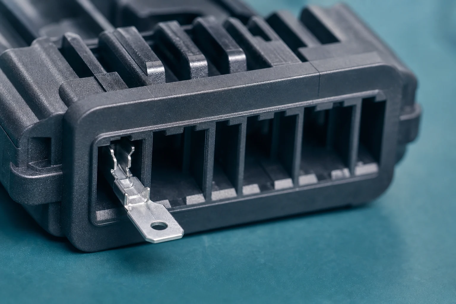
Back-out can begin when the terminal is not fully inserted, when a lance has been damaged or has not engaged its housing feature, or when the contact and cavity are not the intended pair. A terminal that appears present at the rear of a connector may still be short of its intended locked position.
Visual cues must be tied to the controlled design rather than to informal assembly habits.
Part 3. How do primary lances and housing windows work together?
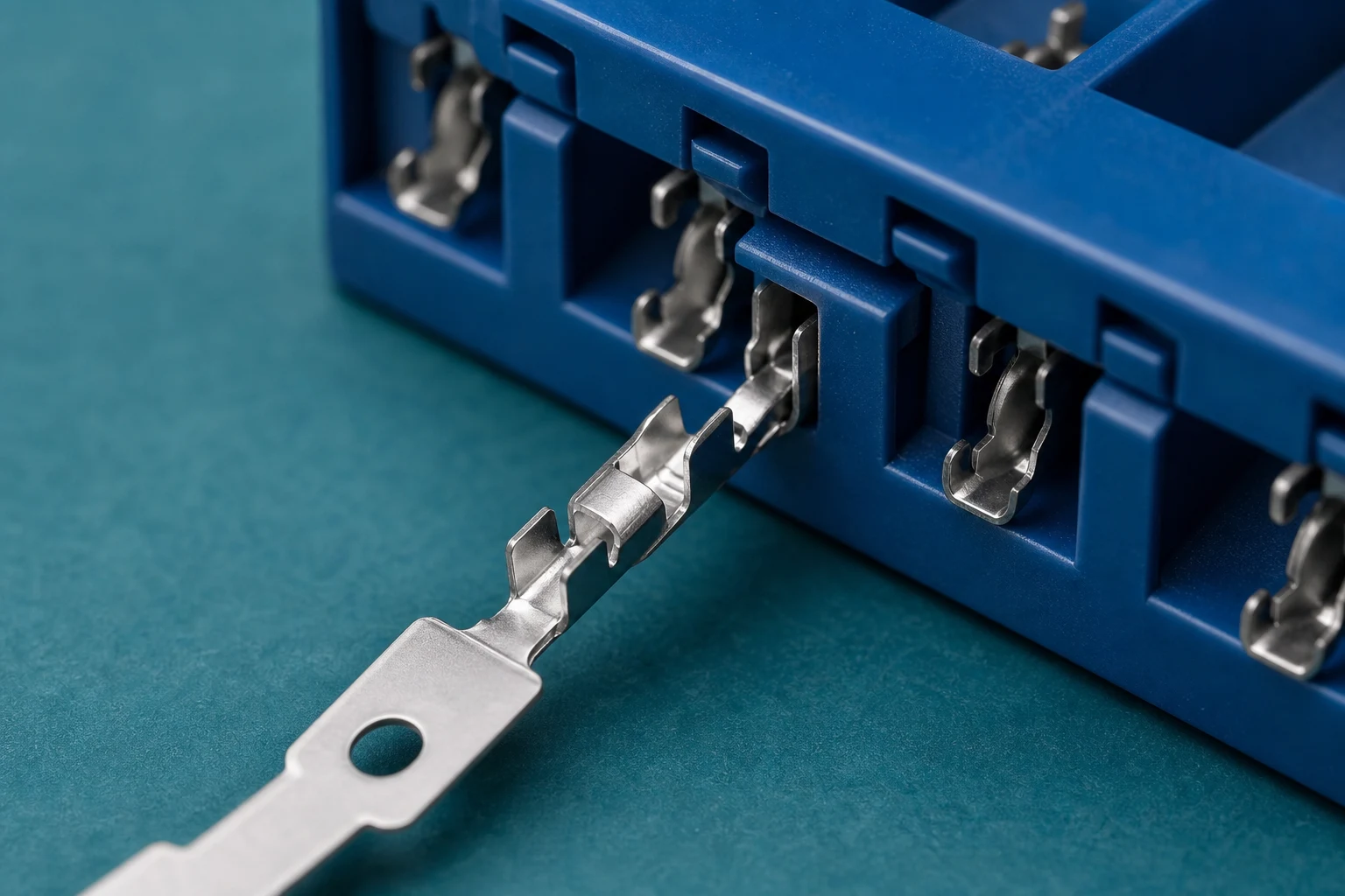
A primary lance normally engages a defined feature in the housing to resist rearward movement. The engagement depends on the terminal orientation, the shape and condition of the lance, the cavity window, and insertion depth. Treat the terminal and housing as a matched interface; a general terminal family name does not prove compatibility. For a related selection reference, see How to Depin Automotive Connector?.
Part 4. Why can wire dress create a retention problem?
A sharply bent wire, strained rear seal, tight bundle, or unsupported service loop can transmit force to the terminal after insertion. Review wire exit direction, bend space, seal position, clamp locations, and connector handling so that installation does not load the retention feature beyond its intended role.
| RFQ field for retention |
Minimum detail |
Why sourcing needs it |
| Contact set |
Female terminal P/N, housing P/N, cavity position |
Confirms the matched retention interface |
| Insertion proof |
Method, depth reference, and visual or tactile check |
Separates “present” from “locked” |
| Wire envelope |
Exit angle, bend radius, seal location, clamp points |
Shows whether routing loads the lance after release |
| Acceptance |
Retention check, sample lot, and nonconformance route |
Aligns SQE and engineering release criteria |
Part 5. When is secondary retention essential?
Secondary retention is especially relevant when the specified connector system uses a separate assurance feature to help confirm or reinforce terminal position. Whether it is essential depends on the selected housing, contact family, environment, and controlled application requirements. It should not be added as a generic substitute for correct primary-lance engagement. For a related selection reference, see Positive Locking Terminals: Where Secondary Retention Is Essential.
Important: Retention guidance supports component selection and inspection planning — it does not approve a finished harness, connector assembly, or field repair without the programme drawing and acceptance record (IPC workmanship review context).
Part 6. How should insertion and retention be verified?
Define the insertion method, allowable force, visual or tactile confirmation, cavity inspection, and any retention check required by the programme. Record what happens when a contact is misoriented, damaged, or fails to reach its seated position instead of relying on ad hoc rework.
Part 7. Which ZUCH route supports component discovery?
Start with ZUCH’s Female Terminal catalogue and the broader product index when you need to identify candidate contact families for a retention review. Use these pages to narrow component options before requesting samples or drawing-controlled confirmation.
RFQ inputs
- Female terminal and housing references with cavity position and orientation.
- Drawing revision, wire gauge, strip length, and crimp specification.
- Routing, seal, service loop, and environmental constraints affecting the contact rear.
- Required retention inspection, sample lots, acceptance criteria, and records.
- Change-control and disposition rules for damaged lances or rejected cavities.
Fit Boundary
This article explains back-out causes and buyer-side retention checks for female contacts. It is not an engineering release, compliance certificate, or proof that a listed terminal is approved for your finished assembly. Request controlled documentation through ZUCH’s apply-sample page or contact form.
FAQ
What is terminal back-out?
It is rearward movement of a terminal from its intended housing position, often caused by incomplete insertion, damage, mismatch, or loading from the wire or bundle.
Can a female terminal lock without looking fully seated?
A correct lock position must be confirmed against the controlled housing and terminal design. Appearance alone may not prove full engagement.
What is a primary lance?
It is a retention feature on the contact that engages a mating feature in the housing to resist withdrawal after insertion.
Does a secondary lock replace the primary lance?
No. A secondary feature works within a connector system that still requires correct contact selection, orientation, insertion, and primary retention.
Why does wire bend radius matter near a connector?
A tight bend or strained bundle can apply rearward or side load to the contact, reducing the margin for stable retention.
How can a buyer specify retention checks?
Provide the controlled terminal and housing references, insertion method, inspection criteria, any required retention method, records, and the nonconformance route.
Can a damaged lance be repaired in place?
Use only the programme-approved disposition. Uncontrolled reshaping can change engagement and should not be assumed acceptable.
References
 Zhejiang ZUCH Technology Co., Ltd.