Zhejiang ZUCH Technology Co., Ltd.
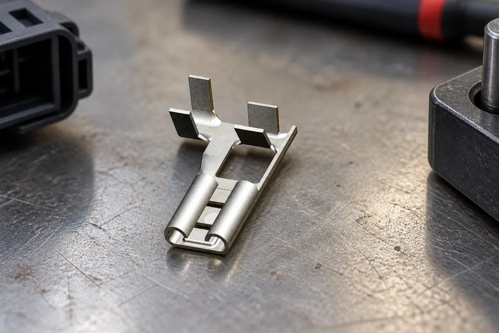
When a harness repair engineer in Munich repinned a body-control connector, an apparently seated terminal backed out during vibration; the root cause was crimp inspection, pin orientation, secondary-lock engagement, and post-repair continuity—not simply a bad housing.
Summary: Re-pinning is a controlled repair, not a matter of pushing a new contact into an old shell. Identify the exact cavity and terminal, remove the old contact without damaging the housing, make a specification-compliant crimp, seat the contact until its lance locks, close the secondary lock, and verify continuity and retention. As a practical rule, inspect every repaired circuit at 100% and use the wire range and crimp dimensions specified by the terminal maker; USCAR-2 and IEC 60512 provide useful test frameworks, but neither is a universal “repair certification.”
In an automotive harness, the housing aligns and protects the terminals, while each terminal creates the electrical interface. Re-pinning may follow water intrusion, collision damage, an option change, or an assembly error. One poorly placed contact can create an intermittent fault that is expensive to reproduce, so the process matters to technicians and teams qualifying connector pins for automotive repairs.
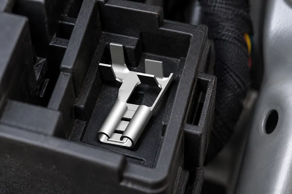
Why connector family, cavity map, and terminal type must be confirmed before depinning
Start with the vehicle wiring diagram, harness drawing, or connector record. Photograph the wire side and mating face; mark cavity numbers and note seals, wedges, CPA devices, and keying. Similar-looking housings may use different terminal sizes, plating, or wire ranges, so visual matching is inadequate.
What circuit and service details should be recorded before removal?
Record wire color, cross-section, insulation diameter, and circuit function. Check for heat, fretting, corrosion, plating loss, or a deformed contact. Replace a cracked housing rather than trusting a re-pin. Isolate the vehicle according to OEM instructions; airbag, high-voltage, and other safety circuits require trained personnel.
Choose the terminal by connector family and wire specification, not amperage alone. Confirm contact gender, interface, seal diameter, conductor range, plating, and required applicator. Preserve wire length and avoid an unplanned splice inside a sealed branch.
Do not treat an empty position and a wired position the same way. A spare cavity may still need a cavity plug, rear seal, or secondary-lock position to preserve environmental performance. If the repair changes the populated-cavity count, update the cavity map before any continuity test so the next technician can distinguish an intentional spare from an open circuit.
How to remove the old contact without damaging retention features
Use the specified extraction tool from the correct face to depress the primary lance, then pull the wire gently from the rear. Twisting or prying can spread the cavity or damage the mating face. Compare old and new parts; discard contacts with damaged beams, plating loss, or a distorted lance.
How should the conductor and seal be prepared for a controlled crimp?
Strip only the length specified on the terminal drawing. Stray strands, nicked copper, or insulation under the conductor barrel reduce reliability. Cut oxidized wire back to clean copper, provided it still reaches without tension. Use a seal matched to the insulation diameter.
Crimp with the approved hand tool, die, or production applicator. The conductor wings should be symmetric and uncracked; insulation wings should support, not cut, the jacket. Verify crimp height, width, bellmouth, brush length, and pull force against the maker’s drawing. Production may use crimp-force monitoring; service work should use a documented sample pull test. The right tool is the one validated for that contact and wire range.
| Checkpoint | Acceptable evidence | Common failure signal |
|---|---|---|
| Conductor placement | All strands inside the conductor barrel; brush visible at the inspection window | Strands folded back, missing, or trapped under insulation |
| Crimp geometry | Specified height/width, centered wings, smooth bellmouth | Over-crimped barrel, cracks, loose wings, or uneven symmetry |
| Insulation support | Jacket held without cutting or crushing the seal | Insulation in conductor crimp or unsupported wire flex |
| Wire and seal fit | Wire range and seal diameter match the terminal drawing | Seal pulled through, torn, or too loose to resist moisture |
For a deeper process sequence, see our guide to how to crimp automotive terminals. It should complement—not replace—the connector manufacturer’s application specification.
How TPA, CPA, and retention checks prove the new terminal is actually seated
Orient the contact as the cavity drawing shows and push it straight in until the primary lance clicks. A light tug, within maker guidance, should not move it. Never force an early stop; suspect an inverted contact, bent lance, blocked seal, or wrong terminal.
Install the secondary lock, CPA, or wedge after all cavities are populated. It should close with normal hand pressure and sit flush. If it does not, find the high terminal; never shave plastic or omit the lock. Confirm equal contact heights at the mating face.
Terminal-position assurance features are useful because terminal back-out commonly starts with a contact that was not fully loaded. Treat the secondary lock as an inspection aid, not a cure for the wrong terminal: it should confirm seating and add retention backup, while a connector-position assurance feature confirms the mated housings remain locked.
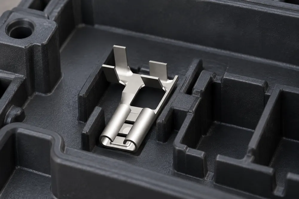
Reassemble seals, backshells, and strain reliefs in order. Provide service slack without a loop that can rub. Preserve specified twist and shielding on communication wires. The connector should mate smoothly; abnormal force is a diagnostic clue.
Which electrical and mechanical checks prove the repair worked?
With the circuit de-energized, perform point-to-point continuity and compare resistance with the OEM limit or a known-good circuit. Test adjacent circuits for shorts and follow the service procedure for shielded or twisted-pair networks. After reconnecting power, scan for diagnostic codes and repeat the original operating condition.
A retention test detects a contact that clicked but did not capture. Validation builds may also require pull, vibration, or thermal-cycle tests. IEC 60512 describes connector test methods, while USCAR-2 is commonly referenced for automotive terminal performance. Record tool ID, terminal lot, wire size, crimp measurements, electrical results, and inspector/date.
| Repair approach | Electrical confidence | Mechanical risk | TCO tendency |
|---|---|---|---|
| Re-pin with new terminal and validated crimp | High when cavity map and continuity checks are documented | Low to medium; depends on housing and lock condition | Usually lowest when the shell is serviceable |
| Reuse an old terminal | Uncertain after prior crimp or corrosion | Medium to high; lance and plating may be weakened | Low unit cost, but higher comeback and labor exposure |
| Replace complete pigtail or connector assembly | High if supplied to the correct specification | Low, with fewer disturbed cavities | Higher parts cost; can reduce diagnostic and warranty time |
| Temporary splice or improvised contact | Variable and difficult to validate | High in vibration, moisture, or heat | Lowest immediate spend, highest lifecycle risk |
This is a decision aid, not a price promise. Access labor, downtime, traceability, and a returned vehicle can outweigh the terminal’s unit price.
Which standards and compliance claims matter after a connector repair?
Standards explain how performance is measured; they do not automatically approve a repair or certify a supplier. SAE USCAR-2 covers requirements and tests for automotive electrical terminals. IEC 60512 provides connector test methods for electrical, mechanical, and environmental performance. A more restrictive OEM specification remains controlling.
Destination-market rules also matter. The U.S. National Highway Traffic Safety Administration publishes safety and recall information. Confirm the vehicle market, voltage class, intended use, and safety-system obligations before making claims. Calling a terminal “USCAR tested” without a defined report, lot, and scope creates warranty, audit, and misrepresentation exposure.
What should a repair team standardize before repinning at scale?
- Standardize identification: retain cavity maps, terminal part numbers, wire ranges, seal sizes, and approved alternates in the work order.
- Validate tooling: tie each contact to a die or applicator, calibration interval, crimp-height limit, and sample pull-test method.
- Protect the process: use ESD, cleanliness, lighting, and safe isolation controls appropriate to the vehicle system; separate high-voltage work from ordinary harness service.
- Build in proof: require visual inspection, retention check, continuity/isolation results, and a traceable sign-off before release.
- Choose a responsive source: ask for drawings, samples, material/plating information, and application support; do not substitute an unverified “equivalent” by appearance.
ZUCH is a connector manufacturer that can be considered when a program needs configurable electrical automotive connectors, documented part data, and sourcing support. Evaluate samples against your own cavity, wire, sealing, and test requirements; no supplier statement replaces validation in the target harness.
For related repair decisions, review automotive electrical connector repair and the overview of automotive connectors and terminals.
Frequently asked questions
How do I repin an automotive connector?
Identify the cavity and exact terminal, release the primary lock with the correct extraction tool, crimp a new contact to the specified wire range, and insert it in the correct orientation. Close the secondary lock, then verify retention, continuity, and isolation before functional testing. Follow the OEM procedure for airbags, high-voltage systems, and other safety circuits.
Can I reuse an old terminal when repinning a connector?
Reuse is generally discouraged because the original crimp, lance, plating, or contact beam may have been stressed or corroded. If an OEM procedure explicitly permits reuse, inspect and test it against that procedure; otherwise install a new, correctly specified terminal.
How do I know the new connector pin is fully seated?
You should hear or feel the primary lance engage, see the contact at the correct mating-face height, and pass a gentle retention tug test. The secondary lock or CPA must close flush without force. A contact that sits proud, recessed, or prevents mating indicates a wrong orientation, blocked seal, or damaged cavity.
What crimp tool is needed for automotive connector pins?
Use the die set or applicator specified for the exact terminal family, conductor range, insulation diameter, and seal design. Generic pliers can alter crimp geometry and invalidate pull-force assumptions. Keep calibration records and verify crimp height and sample pull force according to the terminal drawing or control plan.
Why does a new terminal pull back out of the connector?
Typical causes are an inverted contact, a bent or depressed lance, incomplete insertion, an incorrect terminal, or a secondary lock that was not installed. Remove the contact, inspect the cavity and lance, and replace damaged parts rather than forcing the lock or adding adhesive.
Should I test continuity after repinning a connector?
Yes. Check point-to-point continuity, contact resistance where specified, and isolation from adjacent circuits with the system de-energized. Then perform a powered functional test or diagnostic scan under the original fault conditions and record the results.
Sources for connector repair standards and sourcing decisions
- SAE USCAR-2: Performance specification for automotive electrical terminal systems
- IEC 60512 connector test methods
- NHTSA vehicle-safety resources
- OEM wiring diagrams, connector drawings, and service information for the target vehicle
A reliable re-pin is proven twice: the terminal must stay locked mechanically, and the circuit must perform electrically after the harness is back in motion. When you are selecting a repeatable connector platform or replacement terminals, explore ZUCH products and contact the team with your cavity map, wire specification, and validation requirements.