Zhejiang ZUCH Technology Co., Ltd.
Illustrative scenario only; this is not a documented field case from the featured supplier. When a harness and controls engineer in Hamburg consolidated a panel-to-door interface onto one connector, the first pilot build looked tidy but failed continuity checks on one circuit within minutes. The team first suspected a defective connector. The real problem was upstream: the specification did not lock the mating interface, terminal-wire combination, retention checks, or acceptance test.
Summary: Treat “bridge combination connector” as a supplier-specific description, not a universal connector class. Freeze the electrical, mechanical, environmental, assembly, and service requirements; then verify them against the supplier drawing and applicable test reports. IEC 61984:2008 has a defined scope—certain connectors above 50 V through 1,000 V AC/DC and up to 125 A per contact—but those numbers are not a rating for an unidentified product. Do not release a part from its name or image alone.
What must “bridge combination connector” mean in your design?
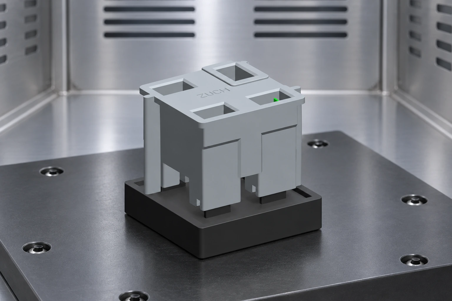
The phrase does not establish a standardized interface, contact system, circuit arrangement, or performance level. In practical sourcing, it may describe a combined or multi-section assembly that brings several connection functions into one interface. The pictured item can be described only as a gray, CAD-style multi-cavity connector assembly. Its appearance does not prove contact count, materials, current, voltage, sealing, certification, dimensions, or intended application. A 187 all-in-one connector likewise needs its own interface drawing; the name alone does not identify a mate.
The mechanism is easier to evaluate when separated into five interfaces: housing-to-mate geometry, contact-to-contact engagement, terminal-to-conductor termination, contact retention inside the housing, and assembly-to-equipment mounting. A failure at any one interface can look like a “connector failure” even when the real cause is an incompatible terminal, insufficient insertion, harness strain, tolerance stack, or an acceptance plan that omitted the relevant condition.
Start with a controlled interface drawing. It should identify the supplier part numbers for both halves, orientation and keying, cavity map, terminal family, allowed conductor range, strip length and tooling, retention features, mounting datums, mating clearance, and any accessories. Where sealing or shielding is required, add the exact components and assembly states that make the claim valid. The drawing and report—not the product label—are the product-specific evidence.
When does a consolidated interface earn its place?
A combined connector can reduce the number of separate mating actions and help mistake-proof a harness, but consolidation also concentrates dependency. One interface change may affect several circuits, and a single service replacement may disturb otherwise healthy connections. The decision should therefore compare assembly and service risk, not just connector count.
| Architecture | Potential advantage | Primary trade-off | Best fit when |
|---|---|---|---|
| Combined multi-cavity connector | One defined disconnect point; fewer separate mating actions | Higher consequence if keying, retention, or one common interface is wrong | Circuits share a service boundary and can be verified as one assembly |
| Several separate connectors | Functional separation and selective replacement | More mounting space, labels, and opportunities to cross-connect | Power, signal, or service groups need independent handling |
| Terminal block or fixed pass-through | Field-visible termination and circuit-by-circuit access | Slower disconnect and greater dependence on installation workmanship | Frequent individual-circuit changes matter more than rapid module exchange |
| Application-specific rectangular interface | Can align keying, mounting, and circuit layout to the equipment | Engineering validation, tooling, and change-control effort | Volume and lifecycle justify a controlled custom interface |
Total cost should include connector parts, terminals, seals and accessories, application tooling, operator time, inspection, rework, test fixtures, service access, spares, and engineering-change exposure. An illustrative comparison is: lifecycle interface cost = purchased parts + assembly labor + verification + expected rework + service handling + change cost. Insert your own build times, defect data, service frequency, and program volume; without those inputs, a lower piece price does not demonstrate a lower total cost.
How should engineers select and document the interface?
- Build a circuit schedule. Record voltage type and maximum, continuous and transient current, conductor size and insulation diameter, signal sensitivity, grounding or shielding needs, and circuits that must remain physically separated. Record simultaneous loading rather than evaluating every position as if it operates alone.
- Define the physical envelope. Set mating direction, usable panel space, rear wire-bend and service clearance, mounting constraints, harness pull direction, allowable motion, and the maximum number of service mating cycles expected.
- Describe the environment. State ambient temperature range, contamination, moisture, chemicals, vibration, shock, altitude, indoor/outdoor location, and whether the connector is mated or unmated during exposure. Request a test condition that matches the actual state.
- Control termination and assembly. Approve the terminal, wire, crimp tool and applicator settings as a combination. Define pull-force or retention checks, cavity insertion confirmation, secondary-lock position, marking, and end-of-line electrical testing.
- Write the evidence package before requesting a quote. Ask for the supplier drawing, part-number BOM, test plan, report numbers and tested configurations, sample approval records, and change-notification terms. A report for a different cavity layout, terminal, wire, seal, or test severity may not transfer.
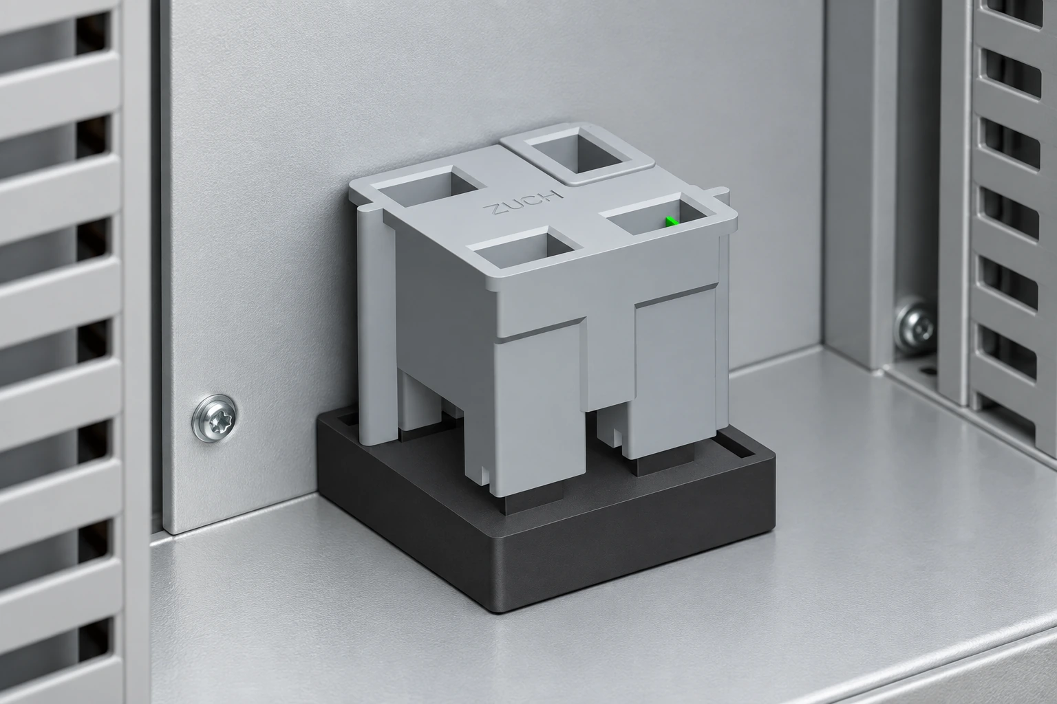
For a late-stage sourcing review, ZUCH can be approached as one candidate supplier rather than treated as proof by brand. Compare the documented assembly against the broader rectangular connector range and connector categories, then request the drawing and matching test evidence for the exact quoted part number. A CT-S/P0136 single-core connector should be reviewed against its own drawing and part-specific evidence as well.
Which failure modes should a release plan catch?
| Observed risk or symptom | Specification cause to investigate | Verification approach | Supplier evidence to request |
|---|---|---|---|
| Intermittent continuity after mating | Incomplete engagement, contact pushback, strain, or incompatible terminal | Visual/retention checks plus contact-resistance measurements before and after conditioning | Section drawing, terminal compatibility, retention limits, and relevant IEC 60512 method/report |
| Unexpected temperature rise | Load concentration, ambient temperature, conductor mismatch, contact resistance, or insufficient derating | Test the actual circuit loading and wire set; create a current-temperature limit | Configuration-specific temperature-rise or IEC 60512-5-2 Test 5b derating data |
| Wrong mate or reversed orientation | Keying strategy does not distinguish similar interfaces | Attempt foreseeable incorrect mates and inspect labels in the installed position | Mating-interface drawing, key codes, and interchangeability statement |
| Terminal backs out during service | Primary lance or secondary lock not fully engaged; harness loads reach the contacts | Insertion confirmation, contact-retention test, and installed-harness pull review | Assembly instruction, retention requirement, and tool-control plan |
| Moisture or contamination reaches contacts | Seal set, wire OD, blanking, mounting, or mating state differs from tested configuration | Environmental test on the complete, production-representative assembly | Test report naming specimens, state, severity, acceptance criteria, and results |
| Performance degrades after vibration | Harness mass, unsupported span, resonance, or latch movement | Vibration profile with the installed harness, followed by continuity and contact-resistance checks | Fixture description, axis/profile, monitoring method, and before/after results |
What do IEC and UL references prove—and what do they not prove?
IEC 60512-1:2018 describes general preparation, testing, measurement, requirements, and documentation for the IEC 60512 series. It says detailed product specifications select the methods, severities, and permissible limits. Consequently, citing IEC 60512 alone is not a pass criterion. For example, IEC 60512-2-1 Test 2a addresses low-level contact resistance, while IEC 60512-5-2 Test 5b addresses current-temperature derating; the project still needs its configuration, severity, sequence, and acceptance limits.
IEC 61984:2008 addresses safety requirements and tests for connectors within its stated voltage/current and specification conditions. It is not a blanket certification and does not assign ratings to the pictured assembly. UL 1977 may be relevant to component connectors for data, signal, control, and power applications in North American programs, but applicability and any recognition must be verified for the exact product, conditions of acceptability, and current listing record. A test method, a design review, and a certification are different forms of evidence.
Buyers should put the destination market, equipment standard, connector role, load state, pollution and installation conditions, and required third-party status into the compliance matrix. Then ask the responsible product-safety engineer or qualified lab to confirm the applicable edition and test program. Never infer compliance from a logo, family brochure, or visually similar housing.
Frequently asked questions
Is a bridge combination connector a standardized connector type?
Not by that phrase alone. Treat it as a search or supplier term until the manufacturer part number, mating drawing, contact system, and detailed specification define the interface.
Can I select one from a CAD image?
No. A CAD image can help discuss packaging and orientation, but it cannot establish ratings, dimensions, materials, contact count, sealing, standards, or certification. Obtain the controlled drawing and matching test report before approval.
How do I decide whether to combine power and signal circuits?
Start with voltage, current, heat, insulation/spacing, shielding, EMC, fault behavior, and applicable equipment rules. If separation or independent servicing is critical, multiple interfaces may be safer; a custom rectangular connector decision review can help organize the trade-offs.
Why can a connector overheat even below a catalog current figure?
Catalog conditions may differ from your ambient temperature, conductor, number of simultaneously loaded contacts, airflow, termination quality, or aging condition. Use configuration-specific derating data and investigate the mechanisms summarized in this guide to rectangular connector overheating.
What should a buyer send with the RFQ?
Send the circuit schedule, mating and mounting envelope, wire list, environment, required mating cycles, standards matrix, acceptance tests, annual volume and change-control expectations. Ask the supplier to identify every assumption and every report that applies to the quoted configuration.
Authoritative references and next step
- IEC 60512-1:2018—general specification for connector tests and measurements
- IEC 61984:2008—connectors, safety requirements and tests
- UL 1977—Standard for Component Connectors for Use in Data, Signal, Control and Power Applications
A connector name starts the conversation; a controlled interface and evidence package finish the engineering decision. To review a proposed bridge combination connector against your circuit schedule and request the exact drawing and applicable reports, contact ZUCH with your RFQ package.