RAST Connectors on Appliance PCBs: Review Layout, Mating, and Retention
An appliance PCB reviewer can face a misleadingly simple decision: a proposed RAST header has the same pitch as the existing part, so can it use the same footprint? The board may accept the pin pattern while the mating housing, latch movement or wire exit conflicts with the installed enclosure. Discovering that difference after layout release creates another drawing review, sample check or board revision. A RAST connector layout should be reviewed as part of the appliance PCB, mating interface, cable route, enclosure, and service context. A family name or product image cannot by itself establish fit, retention, or release readiness. The following workflow separates those decisions before an alternate is accepted.
Same pitch does not prove interchangeability. First compare the exact header and mating-part drawings with the board pad or hole pattern, then review the housing keepout, mating and latch travel, wire exit, tolerance stack and soldering constraints separately. A shared footprint is defensible only when those controlled requirements match the intended assembly or their differences have been evaluated and approved. IEC 60512-1:2018 places test selection, severity and permissible performance limits in the detail product specification; its generic test framework is not a declaration that two RAST parts are equivalent. Freeze the relevant drawing revisions before asking for samples or layout approval.
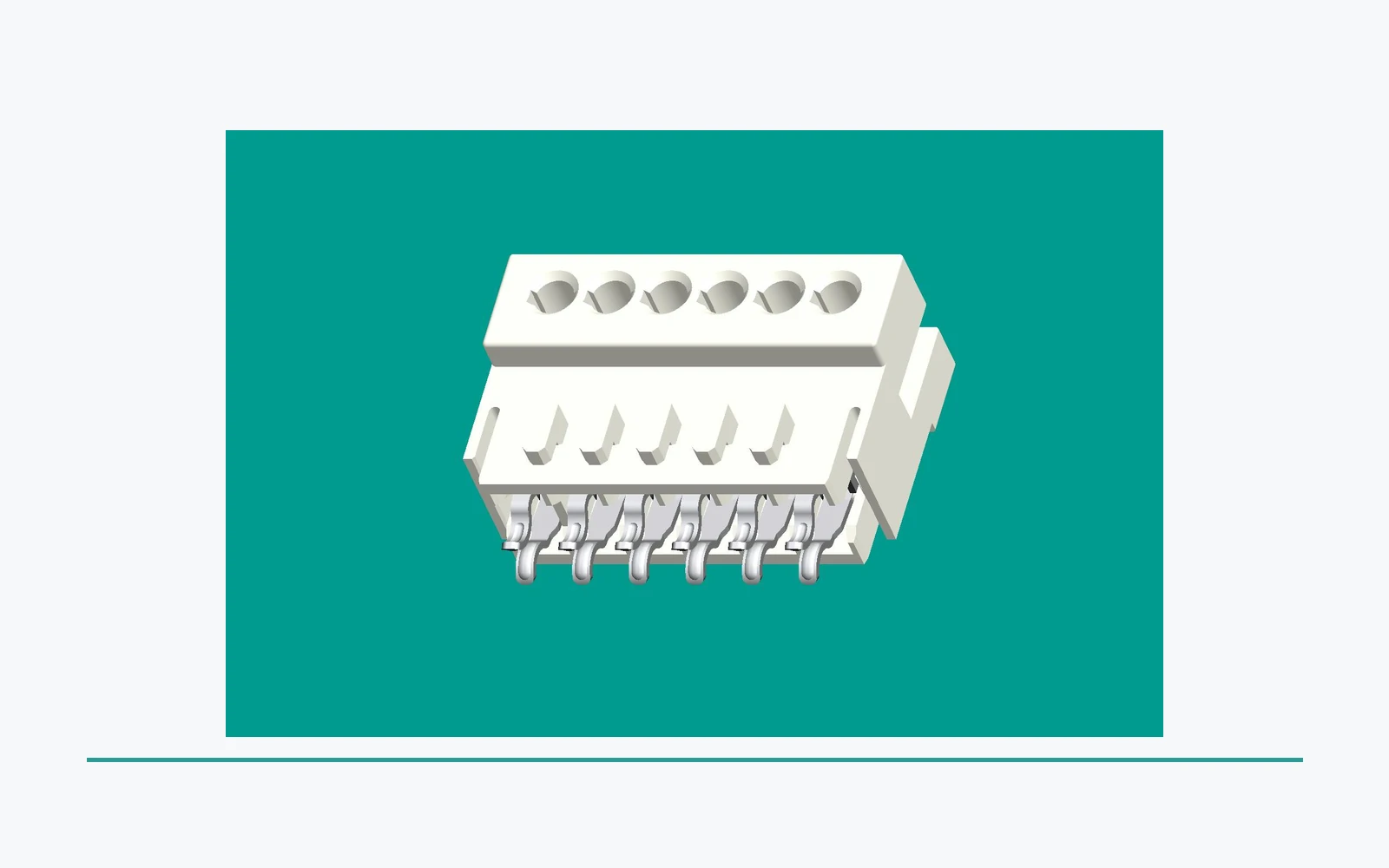
What does this layout review cover?
Which inputs define the RAST connector layout boundary?
Start from the released connector and mating definitions, the intended PCB location, and the surrounding appliance assembly. The layout review should identify the board envelope, interface orientation, cable exit, nearby components, enclosure boundaries, and access needed for assembly or service.
This approach helps engineering and sourcing discuss the same defined interface. It also prevents a broad product-family description from being used as a substitute for the controlled drawing.
| Layout input |
Why it matters |
Controlled record |
| Footprint and orientation |
Defines where the interface sits on the board |
Current PCB layout and revision |
| Mating relationship |
Identifies the matching connector and engagement direction |
Mating drawing and keying information |
| Assembly envelope |
Shows nearby components and enclosure dependencies |
Board, harness, and housing layout |
Treat the footprint as the board attachment definition, not the whole usable connector envelope. The housing outline describes occupied space; the mating path describes moving space; service access describes how an operator can reach and release the interface. Each is a separate review item even when an ECAD library combines them in one package. The workflow below is engineering synthesis, not a manufacturer footprint specification. IEC 60512-1:2018 supplies the test-documentation framework, including connector housings, locking mechanisms, contacts and terminations; it supplies no dimensional equivalence rule for RAST alternatives.
How should the footprint and board envelope be verified?
Review the released footprint with the height, keep-out, routing, component-clearance, and manufacturing constraints defined for the board. The complete assembly, rather than a connector outline alone, determines the space that needs to be preserved.
Any design-rule values belong to the responsible organization’s controlled documentation. This article identifies selection questions; it does not prescribe PCB dimensions or assembly limits.
Important: A connector footprint that appears to fit on a board view is not evidence that the complete PCB, mating interface, enclosure, and intended assembly conditions have been validated. Source: IEC 60512-1:2018 generic connector test specification.
Start with the supplier’s released drawing for the exact board-side part and its specified mate. Match its view direction and datum to the PCB library, confirm pin numbering against the schematic, and compare the recommended board pattern with fabrication data. An apparent match in a top view is not sufficient if a drawing shows the connector from the mating face or underside. Where a feature is not defined, request clarification rather than copying dimensions from a photograph.
| Review layer |
Drawing-based verification |
Decision before release |
| Board pad or pin pattern |
Compare contact positions, numbering, row arrangement, finished-hole or pad definition, locating features and any fixing points with the exact part drawing. |
Accept the library only against controlled board-pattern data; matching pitch alone leaves other features unresolved. |
| Housing keepout |
Place the complete housing outline and its specified tolerances relative to nearby components and enclosure surfaces. |
Reserve the occupied envelope independently of the copper pattern. |
| Mating and latch travel |
Check the mating direction, full insertion path and the movement and access needed for the specified latch. |
Confirm the assembly can mate and release; static clearance is only one check. |
| Wire exit and harness route |
Review the installed mating housing, wire departure direction, supported route and the cable supplier’s bending requirements. |
Keep the actual harness from obstructing mating, latching or service access. |
| Tolerance stack |
Combine the relevant limits for header location, board position, enclosure position and mating assembly using the project’s documented method. |
Check the limiting assembly condition, not just nominal CAD fit; do not invent a clearance allowance. |
| Solder and manufacturing constraints |
Compare termination geometry, board construction, supplier soldering limits and access for the selected process, inspection and rework. |
Resolve process compatibility with manufacturing before finalizing the footprint. |
How should electrical spacing and soldering be separated from mechanical fit?
A mechanical keepout is not an electrical spacing approval. Review clearance through air, creepage along surfaces and solid insulation using the appliance’s documented insulation requirements. IEC 60664-1:2020+AMD1:2025 covers insulation coordination and the determination of these requirements; the public catalogue does not provide the spacing value for this board. The responsible reviewer must establish applicable electrical conditions and the equipment-standard requirements before approving copper spacing or treating housing separation as sufficient.
Likewise, do not infer wave, selective or reflow soldering suitability from the RAST family name. Ask for the exact part’s approved process limits and compare them with the proposed manufacturing profile. Review hole or pad geometry, underside access, inspection visibility and rework access with the assembly team. The IPC document revision table lists J-STD-001, Requirements for Soldered Electrical and Electronic Assemblies, and IPC-A-610, Acceptability of Electronic Assemblies. This verifies their document identities and listed revisions, not solder-joint acceptance limits. Use the contractually specified documents and the actual supplier process information for those decisions.
How do mating direction and retention affect layout?
Check the intended mating direction, keying, engagement path, retention feature, and clearances around the released connector system. Retention depends on the complete specified interface and its application conditions, not on a housing image alone.
Document the interface revision and any dependent components. This makes a prototype or supplier response easier to compare with the intended PCB assembly.
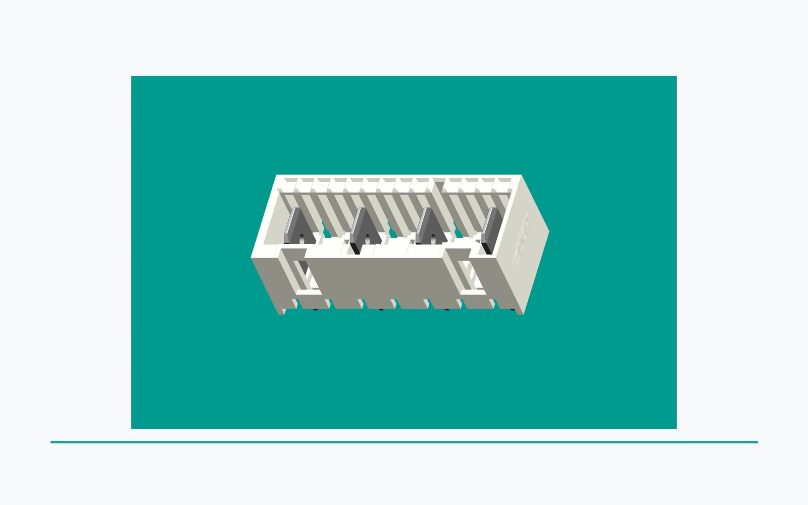
Review mating in the intended assembly sequence, then review unmating in the installed appliance. A header that can be populated before a cover is fitted may still be inaccessible for later release. Keep three records distinct: the housing envelope at full engagement, the swept path during mating, and the space needed to operate the retention feature. Use the specified mate and representative harness; an unconnected header cannot demonstrate these relationships.
If retention or mating performance needs a test, define the exact assembly, sequence, conditions and acceptance limits before commissioning it. IEC 60512-1:2018 explicitly links detail test methods with the detail product specification that prescribes severity and permissible performance limits. It does not set a universal latch-force threshold or certify this board assembly.
How should cable routing and service access be reviewed?
Cable exit direction, bend space, harness support, nearby covers, and service access can all affect a PCB interface. Review them in the installed assembly view, not only in the board CAD view.
This is especially useful where an appliance enclosure limits the path to mate, inspect, or release a connector. The responsible organization must define any controlled service process for the finished equipment.
Cable routing also changes the conditions under which a current-rating statement is evaluated. Ask what local temperature and installed configuration the evidence represents, particularly when the connector sits near heat-producing components or inside a constrained enclosure. IEC 60512-5-2:2002, Test 5b is a method for assessing current-carrying capacity at elevated ambient temperature. Its public scope provides no universal RAST current rating and no board-specific derating curve. Keep thermal evidence separate from a geometric fit check; a routing change may require the thermal review to be reopened.
Send the controlled inputs that allow a supplier response to be compared against the correct interface. The package should identify what is under review rather than assume compatibility from a generic RAST description.
| Inquiry item |
Purpose |
Send with RFQ |
| PCB and mating definition |
Identifies the intended interface |
Footprint, connector, mating drawing, and revision |
| Envelope and routing |
Shows packaging and access constraints |
Board, enclosure, cable exit, and support layout |
| Evidence request |
States program expectations |
Sample objective, requested records, and evaluation needs |
| Change control |
Keeps the inquiry tied to the release basis |
Revision, notification, and traceability expectations |
Ask the supplier to answer against the submitted drawing revision and to identify deviations explicitly. A useful response distinguishes a recommended board pattern, an approved mating pair and application test evidence; one does not replace the others. Include the proposed soldering process and the documented insulation and thermal requirements so procurement does not reduce an engineering substitution to a same-pitch price comparison. The review effort, potential board respin, harness change and repeated verification belong in the sourcing comparison, without inventing a cost-saving percentage.
When should an interface change reopen layout review?
A change to the footprint, mating part, orientation, keying, cable route, enclosure, or intended use can affect the original layout review. Record the difference and route it through responsible engineering before relying on prior evidence.
The same discipline applies when a proposed alternate uses a similar family name. Compare the complete controlled interface, not only the category label.
Which changes invalidate an earlier layout decision?
| Proposed change |
Review to reopen |
Evidence to close the decision |
| Same-pitch alternate header or mate |
Full footprint, pin assignment, housing, keying, latch and tolerance comparison. |
Documented difference review and approval for the exact proposed pair; do not carry over compatibility by family name. |
| Connector rotation, board move or enclosure change |
Mating travel, release access, keepout and the assembled tolerance stack. |
Revised assembly drawing plus a fit/access check against the limiting documented conditions. |
| Wire size, wire exit or harness-support change |
Route, bend requirements, interface loading and relevance of thermal evidence. |
Harness documentation, installed-assembly review and any application tests identified by engineering. |
| Termination geometry or soldering-process change |
Board pattern, thermal process suitability, inspection and rework access. |
Updated supplier process limits, manufacturing review and acceptance basis for the actual assembly. |
Use this checklist as a change-review gate, not a substitute for qualification. Close drawing differences before ordering production quantities, and identify which previous records remain applicable. If the supporting report used a different mate, board construction or installation, engineering must determine whether additional evidence is needed. Supplier performance elsewhere does not establish performance of the proposed ZUCH assembly.
How can buyers prepare a controlled ZUCH RAST inquiry?
ZUCH’s RAST connectors route lets a buyer locate relevant connector families before the controlled PCB review. It does not confirm board compatibility, retention performance, availability, validation, or approval for a particular appliance.
For a PCB-focused inquiry, send the current layout and mating drawings, board and enclosure envelope, cable routing and access constraints, sample objective, requested records, and change-control requirements through ZUCH’s sample request route. The IDC versus crimp RAST guide covers the related termination-review inputs. For a related technical reference, see Quick-Connectors for Serviceable Assemblies: Review Access and Replacement Inputs. For a related technical reference, see Sealed vs Open Rectangular Connectors: Define Environmental Inputs First.
FAQ: What do buyers ask about RAST PCB layout?
Does a RAST connector family name define PCB fit?
No. Confirm the released footprint, mating interface, orientation, envelope, routing, and program evidence for the intended assembly.
Review the controlled footprint, mating path, component and enclosure clearances, cable exit, tooling, and access requirements.
Why does mating direction matter?
It affects keying, engagement path, clearance, cable routing, and the ability to inspect or service the installed assembly.
Does retention depend only on the connector housing?
No. Retention must be considered with the specified mating system, board, enclosure, harness, and application conditions.
Should cable routing be part of PCB review?
Yes. Cable direction, bend space, support, and nearby hardware can affect the connector interface and access.
It should identify the controlled footprint, connector and mating definitions, orientation, relevant envelope, routing constraints, and revision.
Provide the current footprint and drawings, mating definition, board and enclosure layout, routing and access limits, sample objective, requested records, and change-control expectations.
Only when the controlled drawings and the intended assembly review support that decision. Compare the complete pad or pin pattern, numbering, fixing features, housing, specified mating part and process constraints. Equal pitch is one matched dimension, not proof of mechanical or electrical interchangeability.
There is no universal value established by these sources. Use the exact header and mating-housing drawings to determine the engaged height, insertion path, latch operation and wire exit, then account for the documented board-to-enclosure tolerance stack. Review electrical insulation spacing separately; physical headroom alone does not establish compliance.
Can a RAST header use any PCB soldering process?
Do not assume that it can. Verify the approved soldering conditions for the exact part and review the board pattern and process access with manufacturing. The IPC revision listing identifies relevant assembly documents but does not disclose their workmanship limits or prove this connector’s process suitability.
Does a verified footprint confirm the connector’s current rating?
No. Footprint verification addresses board attachment and associated geometric constraints; current capability needs evidence for the relevant thermal and assembly conditions. IEC 60512-5-2 describes elevated-ambient current-temperature derating assessment, without supplying a universal rating for RAST connectors.
References
- IEC 60512-1:2018 — Generic connector test and measurement framework; detail product specifications establish tests, severity and performance limits, not dimensional interchangeability.
- IEC 60664-1:2020+AMD1:2025 CSV — Insulation-coordination scope covering clearance, creepage and solid insulation; no board-specific spacing is derived from the public catalogue.
- IEC 60512-5-2:2002, Test 5b — Current-temperature derating method at elevated ambient; not a universal rating or a test report for this assembly.
- IPC document revision table — Public names and revision history for assembly documents including J-STD-001 and IPC-A-610; no paid workmanship clauses or acceptance limits were reviewed.
Conclusion
A usable RAST PCB interface is defined by more than its pitch or copper pattern. Begin with the exact header, specified mate and controlled drawing revisions, then verify pin assignments and board attachment before checking the housing envelope, mating travel, latch access and wire exit. Assess the limiting documented tolerance conditions, confirm soldering suitability with manufacturing, and review electrical spacing and thermal evidence independently. Where a drawing, process limit or application report is missing, keep that decision open rather than treating a nominal CAD fit as approval. Reopen the affected checks when the connector, harness, board or enclosure changes. ZUCH’s existing RAST category and sample inquiry routes provide a practical starting point for submitting these controlled inputs; acceptance still depends on the evidence for the intended appliance assembly.
 Zhejiang ZUCH Technology Co., Ltd.