Wafer Connector vs FFC/FPC Connector: Selecting for Vibration and Service Access
A connector can fit the PCB footprint yet be difficult to release after the enclosure is assembled. A flat cable can fit a narrow gap yet load its connector when the cover moves; a discrete-wire harness can pull on a locked housing if its support is misplaced. The wafer connector vs FFC/FPC connector decision therefore needs more than a pitch and height comparison. Engineers and buyers must establish the cable interface, the route for mechanical loads, and the technician’s actual access. This guide compares those conditions before turning to assembly cost, qualification and replacement control.
The short answer is to choose discrete-wire wafer interfaces for suitable branching and accessible housing-level disconnection, and FFC/FPC interfaces for compatible flat-cable routing in a constrained envelope. Neither type is inherently vibration-proof or automatically suitable for repeated service. Verify the particular lock, cable support, board attachment and mating instructions. IEC 60512-1:2018 makes the detail product specification responsible for selected tests, severities and performance limits; a family name is not qualification evidence. Start with the assembled enclosure and exact cable/connector drawings, then validate the configuration that will actually be purchased.
Contents
What separates a wafer interface from an FFC/FPC interface?
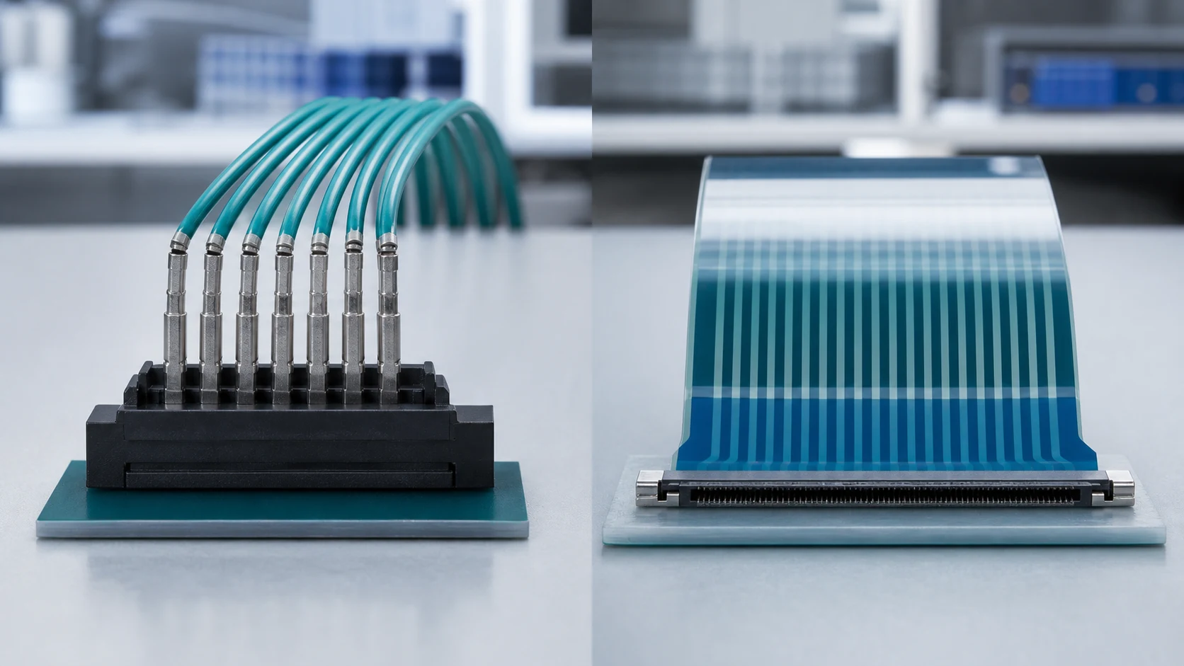
In this comparison, a wafer pair joins discrete crimped wires to a board header, while an FFC/FPC connector terminates a flat flexible cable or printed flex directly. The two differ in conductor construction, retention style, routing behaviour and repair logic. “Wafer” is not a complete interface specification: identify the header, housing and terminals as a controlled set.
FFC means flat flexible cable; FPC means flexible printed circuit. An FFC normally uses parallel flat conductors, while an FPC uses a patterned circuit on a flexible substrate. The connector label alone does not make either cable interchangeable. Connector Supplier’s FFC/FPC overview describes multiple locking styles and both surface-mount and through-hole board terminations, illustrating why a single retention or mounting assumption is insufficient.
| Dimension |
Wafer with discrete wires |
FFC/FPC flat cable |
| Conductor form |
Round wires; mixed sizes only where specified for the terminal set |
Flat conductors or patterned flex circuit; defined mating-end layout |
| Retention |
Friction or positive-lock housings; separate terminal retention |
Actuator, latch or other specified cable-retention mechanism |
| Routing strength |
3D routing and branching, subject to wire and support requirements |
Thin stacks and planned folds; moving routes need suitable cable construction |
| Compatibility checks |
Terminal/housing/header match, wire range, insulation and crimp process |
Pitch, circuit count, cable thickness, stiffener, contact side and insertion geometry |
Will the cable end actually match the connector?
For FFC/FPC, compare the specified mating-end thickness, including the stiffener where required, with the connector drawing. Check exposed-contact length, insertion depth, contact-facing orientation, and any required retention notches or tabs. A cable with the correct pitch can still have the wrong thickness or present its insulated face to the contacts. Also check which side carries exposed contacts at both ends of the cable against the two board connectors; rotating or folding the cable is not a substitute for a verified circuit mapping.
For a discrete-wire assembly, match each terminal to its housing cavity and permitted wire/insulation combination. Confirm header keying and circuit assignment separately. Mechanical insertion does not prove a correct crimp, terminal seating or electrical pinout.
How do cable support and board attachment affect vibration?
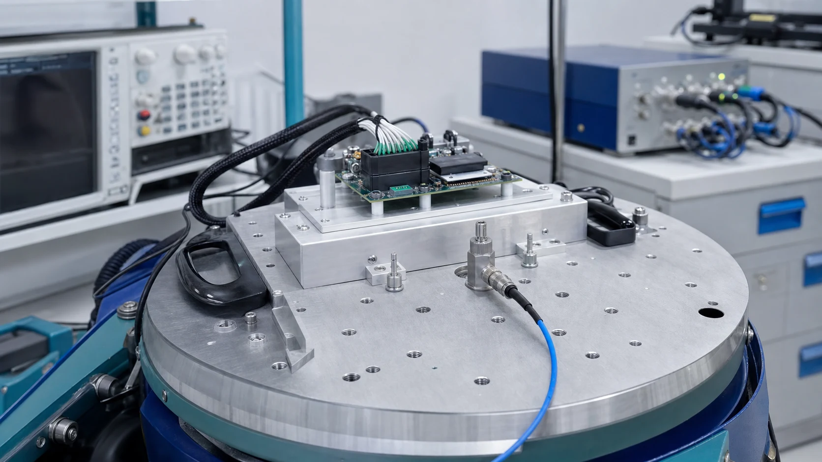
A positively locked wafer housing can resist unintended unmating, and wire strain can be managed with clamps near the interface. That does not establish vibration performance: unsupported harness mass can still load the contacts, housing and header attachment. Flat cables can transmit motion to the connector entry and bend points, so their support and retention also need explicit review. Neither interface is inherently vibration-proof.
Trace the mechanical load from the cable to its support, then through the connector to the board and board mounting. For discrete wires, review clamp location, routing slack and whether a service pull reaches individual terminals. For flat cable, review the supported route, permitted bending near the mating end, and whether enclosure movement pulls or twists the inserted cable. Do not prescribe a universal clamp distance or bend radius; use the exact cable and connector instructions and check the assembled route.
Board attachment is a separate decision from cable locking. Examine the actual header or FFC/FPC connector’s solder tails, mounting tabs or hold-downs, PCB land/hole pattern and nearby board support. Through-hole construction is not automatic vibration approval, and a surface-mount part must not be rejected solely by its termination label. Both need evidence for the intended board and mechanical loads.
Molex’s Connector Contact Retention Guide distinguishes connector-level locking from terminal-level retention and discusses cable strain, incomplete engagement and vibration. A housing latch cannot by itself prove that each crimp terminal is seated. Secondary retention features, where available, must be understood from that family’s instructions rather than assumed to work identically across products.
Can a technician reach the latch or actuator?
A wafer housing can offer a graspable body and, in a positively locked design, a deliberate unlock action. This can suit field disconnection when there is room to grip the housing rather than pull the wires. Flat-cable actuators may require finer access, so plan the release action and operator technique where service is expected. For a related technical reference, see Wafer Connectors: A Practical Guide to Board-to-Wire Applications.
Evaluate access with the enclosure, shields and adjacent cables installed. For a wafer latch, reserve space for the prescribed release travel and straight withdrawal while supporting the board. For FFC/FPC, establish whether the selected mechanism opens by rotation, sliding or another release action; provide its full operating clearance and a usable insertion path. An accessible cable edge is not enough if the actuator is hidden beneath a cover or a technician cannot see that the cable is fully seated.
A service trial should include releasing, removing, reinserting and confirming the connection without levering against the connector or neighbouring parts. Follow the supplier’s method rather than improvising a pry tool. Record whether the replacement unit is a cable, complete harness, connector or board, and verify the specified mating durability against the planned service events.
How do routing space and motion requirements differ?
Flat cables can suit thin stacks and planned fold patterns that discrete bundles cannot readily match. Discrete wires accept three-dimensional routing and branching more naturally, so enclosure geometry is an important selection input. A sliding mechanism, however, needs a cable rated for the intended dynamic use; flexibility for installation is not evidence of repeated-flex capability.
| Stressor |
Wafer-side review |
FFC/FPC-side review |
| Vibration |
Lock engagement, terminal seating, wire support and header attachment |
Cable retention, support, entry strain and connector attachment |
| Frequent service |
Unlock action, housing grip and specified mating durability |
Actuator access, cable alignment and specified mating durability |
| Tight height |
Bundle diameter, permitted wire bending and withdrawal space |
Stack height, fold plan and actuator operating clearance |
| Repeated movement |
Wire construction, bend route and moving-harness support |
Dynamic-flex cable suitability and isolation of the mating end from motion |
Record the route at both extremes of travel, not just in the assembly position. Check for tension, rubbing, pinching and interference with release access. Verify electrical requirements independently: circuit loading, temperature, voltage and signal needs cannot be inferred from the flat or round conductor shape.
What must be validated before approval or substitution?
Ask for evidence that matches the stressors: retention under vibration, mating durability at the service frequency, electrical continuity during relevant movement, and temperature behaviour under load. Treat a borrowed test result as a starting point that the actual configuration must still confirm. Record cable construction, board attachment, support arrangement and test conditions so the result has a defined scope.
IEC 60512-1:2018, Generic specification, provides a framework for connector tests and measurements. Its public catalogue explains that detail product specifications prescribe the tests, severity and permissible performance limits. It does not certify either connector type or supply a universal vibration pass criterion. Agree the relevant methods and acceptance conditions before testing, including how electrical interruptions and post-test mechanical condition will be assessed.
Which changes reopen the approval?
A same-pitch substitute is not automatically equivalent. Changes to a wafer terminal, housing, header, wire size, crimp process or plating require an engineering impact review. For FFC/FPC, include cable thickness, stiffener, contact finish, contact side, retention geometry and actuator design. Changes to PCB attachment, enclosure clearance, cable support or the motion route can also invalidate assumptions even when the connector part number stays unchanged. Retest the affected risks and obtain approval before substitution; the review determines whether targeted verification or broader qualification is necessary.
Important: General guidance cannot approve a specific design or lot. Use controlled drawings, the applicable product/application specifications and a documented acceptance plan. Manufacturer examples establish documentation practices, not ZUCH model ratings or compatibility.
How should assembly and service cost be compared?
Write down the decisive requirements, the option chosen for each interface, and the evidence that closed each risk. That record lets sourcing evaluate alternatives against the real constraints instead of re-opening the design debate. In a wafer connector vs FFC/FPC connector cost comparison, use the assembled and serviceable interface rather than connector unit price alone.
- Cable preparation: include wire cutting, stripping, crimping, terminal insertion and circuit checks for a harness; include the specified flat-cable end preparation, stiffener and any custom retention features for FFC/FPC.
- Board assembly: compare the selected termination process, connector placement, attachment features, inspection access and rework method for the actual PCB design.
- Final assembly: trial alignment, cable insertion, latch closure, confirmation of seating and installation of the required supports. Account for training and fixtures rather than assuming either interface is always faster.
- Service: include enclosure disassembly, release access, replacement-unit availability, reconnection checks and the consequence of a damaged actuator, terminal or board attachment.
- Change control: include tooling changes, drawing updates, samples and the verification needed for an alternate source.
Compare observed assembly and service tasks on representative samples. Do not claim percentage savings without measured process data and a defined volume, labour basis and replacement policy. A simpler cable route may be offset by difficult release access; an easily handled housing may still require more harness preparation.
Which ZUCH documentation should sourcing request?
Use ZUCH’s Small Pitch Connectors category and the live product catalogue to identify relevant connector, terminal or housing component families. These are discovery routes only and do not demonstrate that a specific configuration is approved for the application.
What should the RFQ include?
- Interface list with electrical loading, vibration, motion and service expectations.
- Cable/terminal drawings, circuit assignment, routing envelope, height limits and support or clamp plan.
- Retention style, release clearance and mating-durability requirements per interface.
- PCB attachment requirements, validation evidence, samples and records expected from bidders.
Request the controlled drawing, application instructions and product specification separately. As a documentation example, TE’s 2415838-1 receptacle crimp contact page lists drawing 2415838 Rev A, application specification 114-106638 Rev B and product specification 108-106638 Rev A. It is a wire/cable contact example, not a PCB-header or FFC rating, and its performance must not be transferred to a ZUCH component.
Where does this comparison stop?
This guide supports engineering and sourcing discussion; it cannot replace programme-specific validation, market requirements, or an approval record. Use ZUCH’s sample request route or contact page for controlled component documentation and samples.
FAQ
When should I choose a wafer connector over an FFC/FPC connector?
Consider it when discrete wires, branching or accessible housing-level disconnection dominate the requirement. Mixed wire sizes and positive locking are options only when supported by the selected component set. Confirm support, terminal seating and service clearance rather than relying on the wafer label.
What are the key differences between FFC and FPC connectors?
FFC and FPC primarily distinguish the mating cable or flexible circuit construction, not a universal connector locking mechanism. Some connector families accept both, subject to the specified mating-end geometry. Check the cable thickness, stiffener, contact side and retention features before assuming compatibility.
Which option handles vibration better?
There is no unconditional winner. A locked wafer housing still needs retained terminals, supported wires and a suitable header attachment; an FFC/FPC interface needs compatible cable retention, support and board attachment. Compare test evidence for the installed configurations under the required exposure.
Are FFC/FPC connectors serviceable in the field?
They can be, if the specified release and insertion actions remain accessible in the completed enclosure. Trial the actual replacement procedure and check the connector’s mating-durability specification. Do not force a hidden actuator or treat a damaged lock as acceptable because continuity is present.
Can the two interface types coexist in one product?
Yes. A product may use flat cable in a thin display connection and discrete wires where branching or housing access matters. Approve each local interface against its own cable, electrical, mechanical and service requirements.
Does cost clearly favour one option?
Not universally. Cable construction, tooling, board assembly, inspection, support parts and service access all affect total cost. Compare representative assembly and replacement tasks before claiming a saving.
Can a same-pitch cable or connector be substituted without retesting?
Not on pitch alone. Review dimensional, material, electrical and retention differences, including cable contact orientation and stiffener geometry for FFC/FPC. Engineering should define the affected checks, retesting and approval needed before the substitute enters production.
References
Sources checked 10 October 2026. This qualitative comparison addresses interface architecture and procurement checks, not measured performance rankings. ZUCH is the host supplier; no exact ZUCH cable/connector pair, installed test report or assembly-cost dataset establishes a model-level recommendation here.
Which interface should reach the approved bill of materials?
The useful wafer connector vs FFC/FPC connector distinction is the complete connection architecture, not a promise that round wires withstand vibration or flat cables always reduce cost. First confirm the exact cable, terminal and connector compatibility. Then establish support, board attachment and release access in the assembled enclosure, including the route at every intended position of movement. Compare assembly and replacement work only after those constraints are understood. Finally, qualify the selected configuration against defined electrical, mechanical and service conditions, and keep substitutions inside a documented review and retest process. A latch that closes or a cable that fits cannot replace that evidence. ZUCH’s catalogue, controlled component documentation and samples provide a starting point for that part-specific engineering and sourcing review.
 Zhejiang ZUCH Technology Co., Ltd.