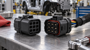
Wafer Connector vs FFC/FPC Connector: Selecting for Vibration and Service Access
Wafer interfaces favour discrete-wire robustness and positive locking, while FFC/FPC interfaces favour thin, flat routing in tight spaces. Pick from vibration, service and routing evidence, not preference.
Contents
Part 1. What separates a wafer interface from an FFC/FPC interface?
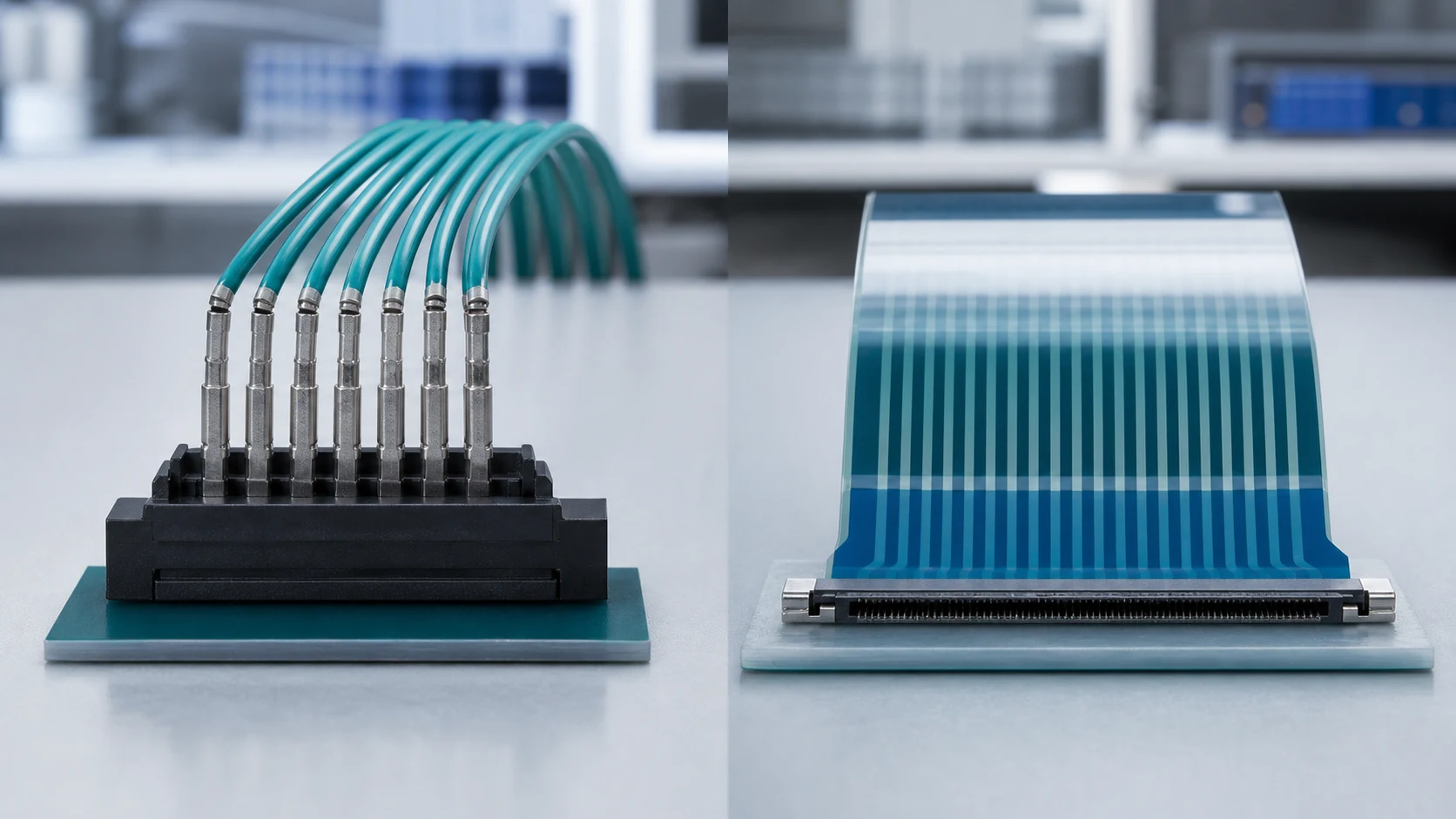
A wafer pair joins discrete crimped wires to a board header, while an FFC/FPC connector terminates a flat flexible cable or printed flex directly. The two differ in conductor construction, retention style, routing behaviour and repair logic.
| Dimension |
Wafer with discrete wires |
FFC/FPC flat cable |
| Conductor form |
Round wires, mixed sizes possible |
Thin flat conductors, fixed layout |
| Retention |
Friction or positive lock housings |
Actuator or latch on flat cable |
| Routing strength |
3D routing and branching |
Thin stacks, folds, sliding motion |
Part 2. How does vibration exposure change the comparison?
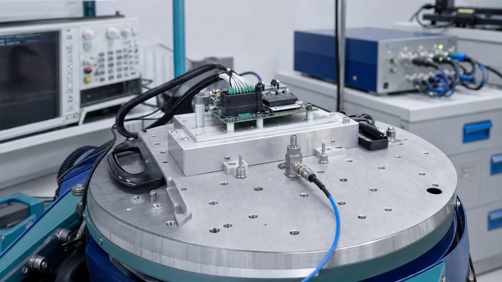
Discrete wires with positively locked housings tolerate shake and handling loads well, and strain can be managed with clamps near the interface. Flat cables concentrate stress at the connector entry and at bend points, so vibration designs need explicit support and retention review.
Part 3. What does service access demand from each option?
A wafer housing offers a graspable body and a deliberate unlock action, which suits repeated field disconnection. Flat-cable actuators are small and can be fiddly or fragile in blind locations, so plan tool access and operator technique where service is expected. For a related technical reference, see Wafer Connectors: A Practical Guide to Board-to-Wire Applications.
Part 4. How do routing space and motion requirements differ?
Flat cables excel in thin stacks, sliding mechanisms and fold patterns that discrete bundles cannot match. Discrete wires accept three-dimensional routing and mixed circuit sizes more naturally, so the enclosure geometry usually decides this dimension.
| Stressor |
Wafer-side review |
FFC/FPC-side review |
| Vibration |
Lock engagement and wire support |
Cable support and entry strain |
| Frequent service |
Unlock action and housing grip |
Actuator durability and access |
| Tight height |
Bundle diameter and bend radius |
Stack height and fold plan |
Part 5. Which validation questions apply before committing?
Ask for evidence that matches your stressors: retention under vibration, mating durability at the service frequency, contact stability after motion cycles, and temperature behaviour under load. Treat any borrowed test result as a starting point that your configuration must still confirm.
Important: General guidance cannot approve a specific design or lot. This is a source-note application of the IPC and TE Connectivity references listed below; apply it through your controlled drawing and acceptance plan.
Part 6. How should the trade-off be recorded for sourcing?
Write down the decisive requirements, the option chosen for each interface, and the evidence that closed each risk. That record lets sourcing evaluate alternatives against the real constraints instead of re-opening the design debate.
Part 7. Which ZUCH route supports this interface comparison?
Use ZUCH’s Small Pitch Connectors category and the live product catalogue to identify relevant connector, terminal or housing component families. These are discovery routes only and do not demonstrate that a specific configuration is approved for your application.
RFQ inputs
- Interface list with vibration, motion and service expectations.
- Routing envelope, height limits and support or clamp plan.
- Retention style and mating-durability requirements per interface.
- Validation evidence, samples and records expected from bidders.
Fit Boundary
This guide supports engineering and sourcing discussion; it cannot replace programme-specific validation, market requirements, or an approval record. Use ZUCH’s sample request route or contact page for controlled component documentation and samples.
FAQ
When should I choose a wafer connector over an FFC/FPC connector?
When discrete wires, positive locking, mixed circuit sizes or frequent field disconnection dominate the requirement.
When is an FFC/FPC connector the better fit?
In thin, space-limited stacks or moving mechanisms where a flat cable’s form factor and fold behaviour are decisive.
Which option handles vibration better?
Locked wafer housings with supported wires are generally more forgiving, while flat cables need explicit strain and retention design; both require configuration-level evidence.
Are FFC/FPC connectors serviceable in the field?
They can be, but small actuators and blind access make technique and tool planning important; assess the real service scenario.
Can the two interface types coexist in one product?
Yes, and they often do: each interface should use the option that matches its local constraints.
Does cost clearly favour one option?
Not universally. Conductor construction, locking features, volumes and assembly method shift the comparison per project.
What evidence should I request before finalising the choice?
Retention, durability and contact-stability results that match your vibration, motion and service profile, plus samples for your own checks.
References
 Zhejiang ZUCH Technology Co., Ltd.