How to Size a Crimp Splice Connector for Stranded Copper Wire
Sizing a crimp splice connector means confirming the conductor, insulation, barrel, die, and finished installation work as one controlled combination. Wire gauge is an important starting point, but it is not enough by itself. Strand construction, insulation diameter, transition-wire conditions, tool profile, and inspection access can all change whether a nominally similar splice is appropriate.
Contents
What does crimp splice connector sizing actually cover?
Connector size is a system definition, not merely a colour band or nominal gauge label. It includes the conductor range, strand construction, insulation outside diameter, barrel design, crimp profile, and required finished geometry. For a transition splice, both conductors need their own approved range check. For a related technical reference, see Wire Harness Branch Design: Choosing Splices, Junctions and Breakouts.
| Input |
Why it affects fit |
Evidence to control |
| Conductor area or AWG |
Sets the starting barrel-fill range |
Wire specification and measured/approved range |
| Strand construction |
Changes how the wire compresses and fills |
Wire construction and preparation requirement |
| Insulation diameter |
Affects support, sealing, and strain-relief fit |
Insulation dimensions and finished envelope |
| Barrel and die |
Form the electrical/mechanical connection |
Controlled terminal and approved tooling |
| Installation |
Adds bend, temperature, vibration, and access constraints |
Drawing and application definition |
TE Connectivity’s crimping guidance treats the contact, wire, and terminating method as related inputs. That is the right frame for an RFQ: define the combination to be evaluated, rather than asking a supplier to infer it from a single wire-gauge label.
How should stranded copper wire be defined?
Record the conductor material, nominal size, strand count or construction, insulation type, and outside diameter. If a wire has a special coating, unusually flexible strand construction, or a stripped-end condition that differs from normal production, state it. A splice that is appropriate for one conductor construction can be a poor process fit for another at the same nominal gauge.
For each side of the splice, specify whether the wire is identical or a transition. Define the allowed strip condition, insertion depth, and whether the insulation must enter a support section. Do not publish generic strip lengths or assume that all stranded copper behaves identically under the same die.
Why do insulation diameter and barrel geometry matter?
The conductor barrel must capture the required strands, while the insulation-support region and finished splice envelope must work with the actual cable. Oversized insulation can prevent correct placement; undersized insulation can leave the cable poorly supported. Both issues become more important where the splice is handled during assembly or routed through a clamp, grommet, or tight enclosure.

Review the finished dimensions as well as the wire entry. A splice can be electrically plausible but mechanically unsuitable if its outside diameter, protection sleeve, or required bend clearance conflicts with the drawing. State whether the program allows a bare barrel, insulated barrel, heat-shrink recovery system, or another protection method.
The correct die creates the terminal manufacturer’s intended barrel form for the selected wire. A hand tool, applicator, or automated press may all be valid only when the terminal, wire, die, setup, and control plan are approved together. Mixing a terminal from one system with a convenient die from another system is not a documented sizing method.
| Tooling question |
Why the buyer should ask |
Release evidence |
| Which die/profile is used? |
Barrel geometry depends on the profile |
Tool/die identification or documented supplier proposal |
| How is setup verified? |
Prevents a correct part from being processed incorrectly |
First-piece or agreed setup record |
| What happens when a check fails? |
Prevents suspect output from continuing |
Reaction and containment instruction |
| How is wear controlled? |
Tool condition can change the formed result |
Maintenance and verification approach |
The connector manufacturer selection guide gives a related framework for asking suppliers for drawing-specific process and change-control evidence.
Which inspection points catch a wrong combination?
Inspection must be linked to the approved splice and acceptance plan. Visual checks may identify incomplete insertion, damaged insulation, exposed strands, or obvious barrel damage. Dimensional, electrical, mechanical, or destructive sampling may be appropriate when the controlled requirement calls for it.
Important: A pull test, crimp-height result, or visual sample only has meaning when the test method, wire, terminal, tool, and acceptance criteria are identified. This is a source-note application of the TE and IPC references listed below; do not transfer a result from a different combination as a blanket approval.
Use IPC as a workmanship reference where applicable, but make the actual RFQ state the governing drawing, sample plan, records, and nonconformance response.
What needs approval before the splice is released?
Before production release, align the component definition, wire definition, tooling, process controls, inspection, and evidence. The release plan should include the change triggers that require reassessment, such as a wire revision, terminal substitution, die replacement, altered protection method, or installation change.
Ask whether a representative sample must be built through the intended process and installed in the actual routing envelope. Then record the approval boundary: sample-only, pilot, or serial production. The cable assembly specification checklist provides a broader RFQ structure when the splice is only one element in a larger assembly.
Which ZUCH product route supports a controlled inquiry?
Use ZUCH’s Solderless Terminals and Connecting Terminals pages to identify a relevant component family, then check the live product catalogue against the controlled wire and process definition. These pages are discovery routes, not confirmation that a specific crimp splice combination is qualified.
RFQ inputs
- Each wire’s material, nominal size, strand construction, and insulation diameter.
- Inline or transition geometry, plus the finished envelope and routing constraints.
- Required protection, service, and environmental conditions.
- Requested terminal/splice, approved tool/die, or documented supplier proposal.
- Sample, inspection, records, approval, and change-control expectations.
Fit Boundary
This article helps buyers define a crimp splice connector sizing question. It does not replace engineering validation, a controlled workmanship plan, or market/customer requirements. A product category or nominal wire range alone cannot approve the completed splice.
Send the controlled inputs through ZUCH’s sample request route or contact page when requesting component documentation or samples.

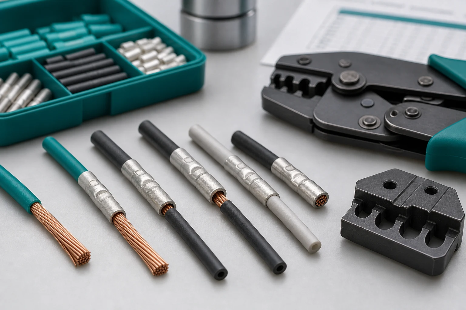
Sizing is a four-part check: conductor, insulation, barrel, and tooling
Wire gauge is only the starting point for a crimp splice. The released combination must also account for conductor construction, actual insulation diameter, splice barrel geometry, and the die or applicator used to form the crimp. Treat these as one controlled combination rather than selecting a size from a gauge chart alone.
| Input |
What to record |
Why the input changes the decision |
| Conductor |
Material, cross-section, strand class and approved wire range |
Different constructions can occupy the barrel differently |
| Insulation |
Outside diameter, jacket material and strip length |
The insulation support and seal may not fit the same way |
| Splice |
Part number, barrel length, material/finish and mating requirement |
The same gauge label can hide different barrel geometry |
| Tooling |
Crimp die/applicator, locator, setup revision and inspection method |
A nominally correct part can fail with the wrong forming profile |
FAQ
Is wire gauge enough to size a crimp splice?
No. Confirm conductor construction, insulation diameter, splice barrel range, strip length, crimp tooling and the required inspection or pull-test method. Gauge alone does not prove a correct crimp.
Why does stranded wire construction matter?
Strand count and lay affect how the conductor fills and compacts inside the barrel. Use the approved wire range and termination guidance for the exact splice and tool combination.
How should insulation diameter be checked?
Measure or verify the actual cable construction against the splice insulation-support or sealing range in the product documentation. Do not infer fit from conductor gauge alone.
What inspection is needed after crimping?
Use the applicable visual, dimensional, pull-test, continuity, and insulation-support checks defined by the program. The exact limits are part-specific and should come from the drawing or governing workmanship document.
What does crimp splice connector size mean?
It describes the approved relationship among the splice barrel, conductor range and construction, insulation dimensions, tooling, and finished installation requirements.
Is wire gauge enough to size a splice?
No. Confirm conductor construction, insulation diameter, each side of a transition splice, barrel geometry, tool/die, and the application envelope.
Why does stranded wire construction matter?
Strand construction affects how the conductor fills and compresses in the barrel. Two wires with the same nominal gauge can need different controlled process conditions.
How should insulation diameter be checked?
Use the controlled wire specification and confirm the insulation fits the selected splice’s support and finished envelope without forcing or leaving the cable unsupported.
Does the crimp die affect sizing?
Yes. The die profile and tool setup form the barrel around the wire, so they must be matched to the selected terminal and conductor combination.
What inspection is needed after crimping?
Use the approved visual, dimensional, electrical, mechanical, or destructive sampling plan for the actual terminal, wire, tool, and application.
What should buyers send in a splice connector RFQ?
Send the wire definitions, connection geometry, protection and routing conditions, terminal/tooling requirement, sample and acceptance plan, records, and change-control expectations. For a related technical reference, see Butt Splices vs Terminal Splices: How to Select an Inline Wire Connection.
Key takeaway
A crimp splice is sized only when the conductor, insulation, barrel, and approved tooling agree. Keep those four inputs together in the drawing, sample plan, and inspection record so a supplier cannot substitute a visually similar but uncontrolled combination.
References
 Zhejiang ZUCH Technology Co., Ltd.