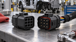
Waterproof Connector Cable Sealing: Grommets, Overmolding and Strain Relief Compared
Waterproof Connector Cable Sealing: Grommets, Overmolding and Strain Relief Compared
Use controlled application inputs and a representative validation plan before treating an interface choice as a release decision.
Contents
Part 1. What must a cable-sealing design define?
Start with the actual interface: cable construction, exit direction, movement, enclosure boundary, installation sequence, and the ingress condition the program must evaluate. A seal is an interface system, so a material name alone cannot demonstrate acceptable field performance.
| Design input |
Information to provide before comparing components |
Why the program must confirm it |
| Mating arrangement |
Counterpart, current drawing revision, cable exit geometry, and function |
The review must represent the assembly that will be built |
| Service environment |
Water mechanism, installation method, handling, access, and movement |
The validation method must reflect the intended exposure |
| Acceptance record |
Sample condition, inspection route, acceptance criteria, and change triggers |
Evidence from a different build cannot be transferred automatically |
Part 2. How do grommets control the cable entry?
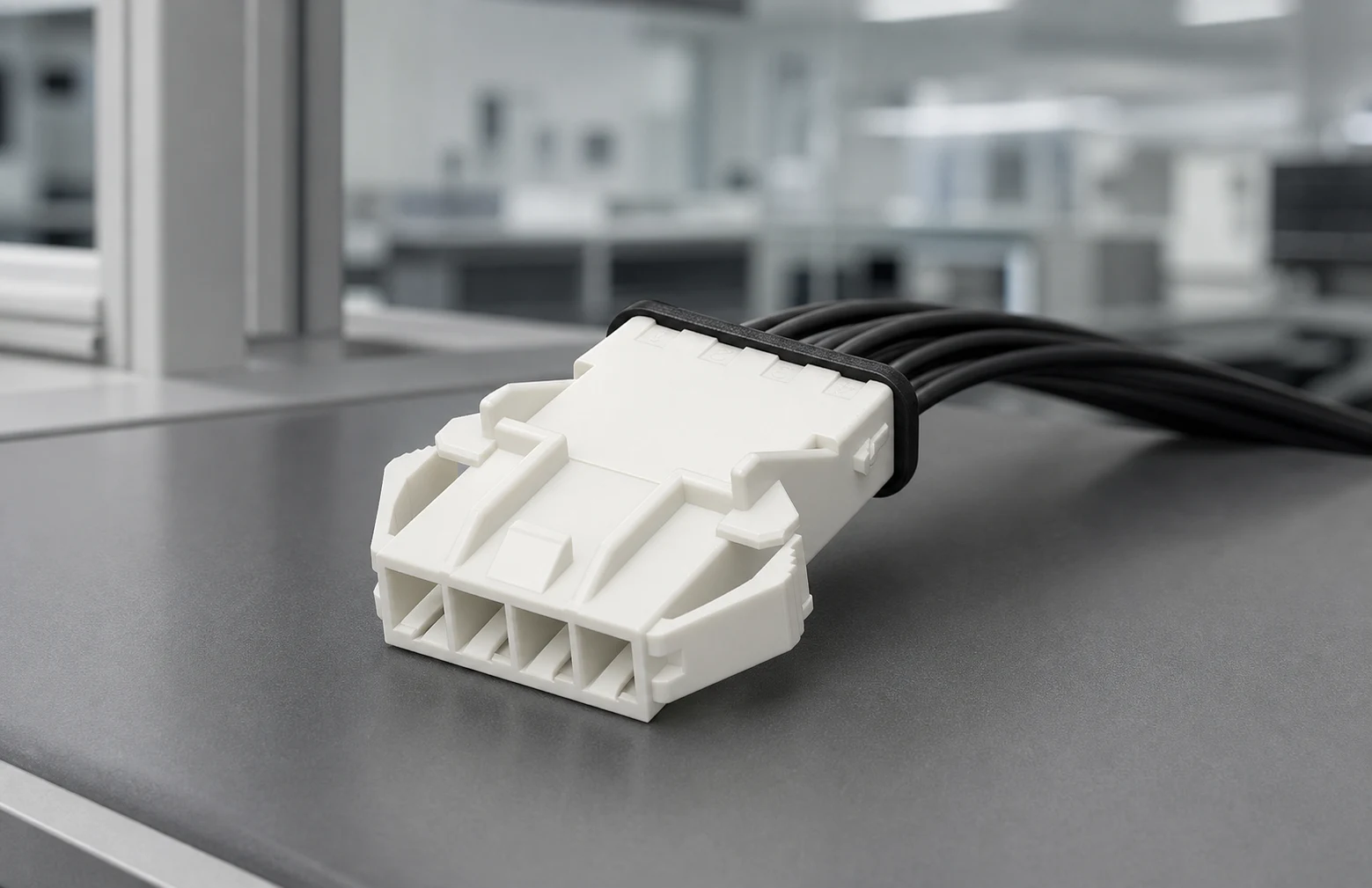
A grommet seals by compressing around a defined cable envelope, so its useful range depends on the cable and the surrounding geometry. Before choosing one, record the cable diameter tolerance, jacket construction, grommet shape, retention feature, assembly method, and any service-access requirement.
The review should also state whether the cable may rotate, flex, or be replaced. Those conditions affect the mechanical interface even when the visible seal looks intact.
Part 3. Where does overmolding change the design review?
Overmolding may combine cable support with environmental protection, but its result depends on cable preparation, material compatibility, process control, exit geometry, and inspection access. Treat the finished assembly as a specific configuration to verify, rather than taking the presence of overmolding as a generic sealing assurance. For a related technical reference, see Sealed vs Open Rectangular Connectors: Define Environmental Inputs First.
Part 4. Why is strain relief separate from sealing?
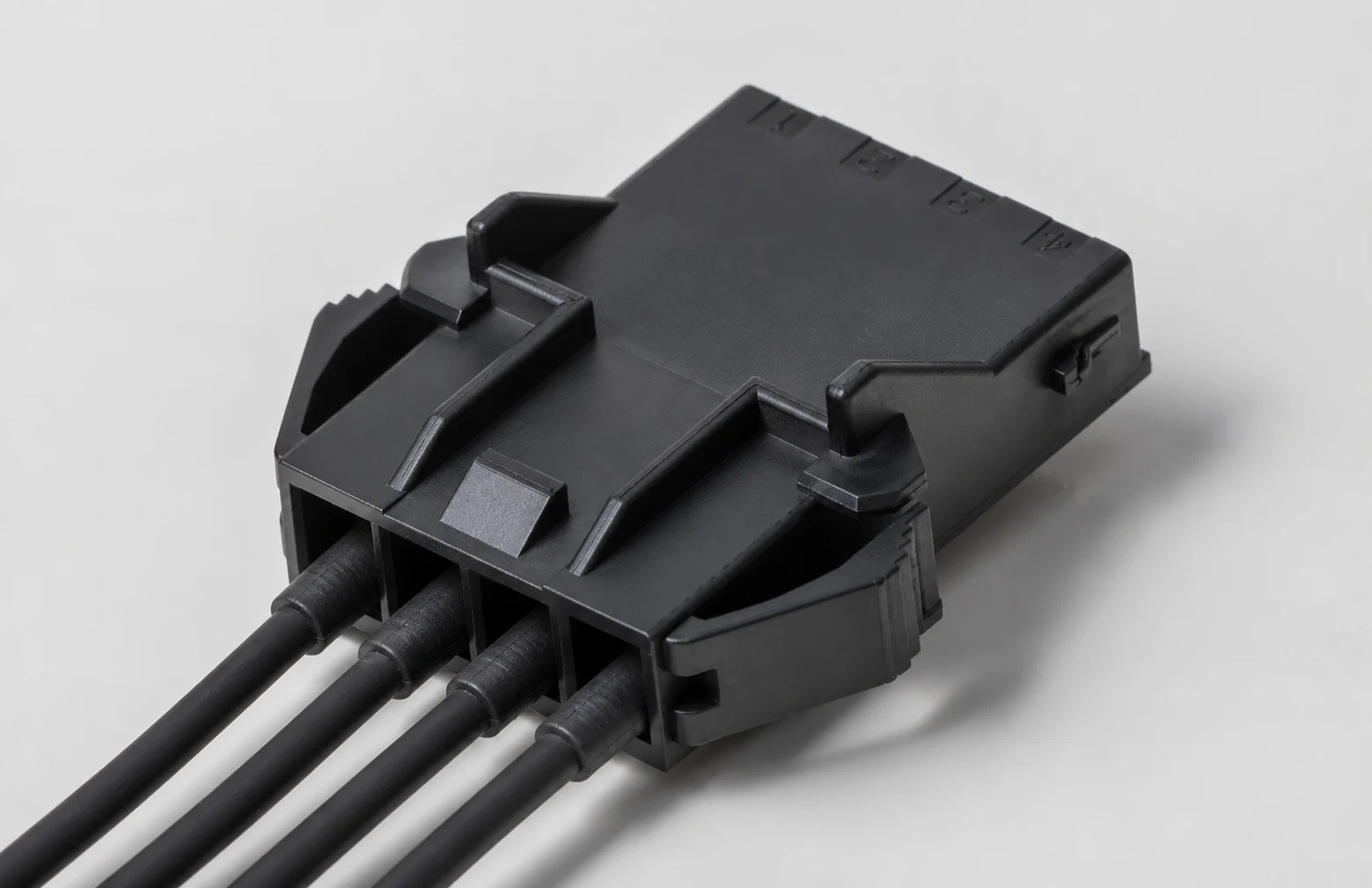
A watertight boundary and a load path solve different problems. Define how handling, routing, vibration, bend, and pull loads are transferred away from the contact termination and sealing interface, then evaluate the representative assembled condition.
| Review question |
Evidence to request from the build |
What remains outside the evidence |
| Does the assembly match the released drawing? |
Current dimensions, mating definition, cable entry, and revision record |
A drawing match alone does not approve the completed equipment |
| Do samples represent field conditions? |
Defined sample build, conditioning sequence, and exposure plan |
A category-level statement is not automatically transferable |
| What happens after a material or process change? |
Deviation route, substitution record, and criteria for reassessment |
The project owner retains the final acceptance decision |
Part 5. Which interfaces deserve a verification matrix?
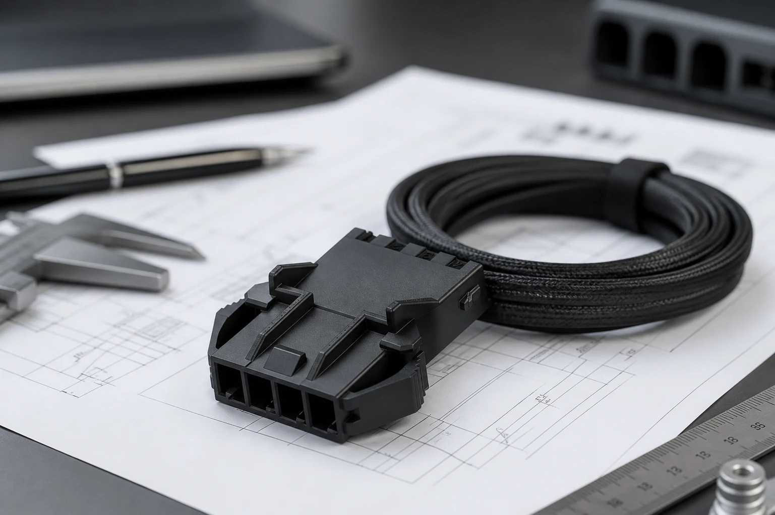
Build a matrix that separates cable-to-seal, seal-to-housing, housing closure, mating interface, and cable-support boundaries. For each boundary, identify the sample build, exposure or conditioning sequence, inspection method, acceptance criterion, and event that requires reassessment.
Important: A component-level sealing statement cannot establish the ingress performance of a finished assembly. IEC’s IP-code framework applies to the stated test conditions, so program owners should retain configuration-specific validation and acceptance records. (IEC Webstore)
Part 6. How should engineering and purchasing control change?
Keep the drawing revision, cable source, material callouts, assembly instructions, inspection points, records, and deviation route aligned. The quotation should identify assumptions explicitly; a cable, seal, or processing-route substitution needs review before it is treated as equivalent.
Part 7. Which ZUCH route supports a controlled inquiry?
For product discovery, review ZUCH’s waterproof connector category alongside the product catalogue. Category browsing can help identify a discussion starting point, but it cannot determine configuration fit or approve an installed assembly.
RFQ inputs
- Current drawing revision, mating counterpart, cable construction, and intended function.
- Exposure mechanism, installation method, routing, service access, and expected mechanical movement.
- Representative sample definition, requested inspection or test evidence, and the acceptance route.
- Material restrictions, documentation needs, change-notification process, and nonconformance handling.
Fit Boundary
This guide supports a bounded engineering and sourcing discussion. It is an input-organizing aid, not an engineering release or equipment approval. Submit relevant configuration details through ZUCH’s sample request page or contact channel when a controlled component discussion is needed. For a related technical reference, see Waterproof Connector Ratings: IP67 vs IP68 vs IP69K for Industrial Equipment.
FAQ
What is cable sealing in a waterproof connector?
It is the controlled interface between the cable and connector assembly intended for the application’s defined ingress conditions; its suitability must be verified on the actual configuration.
Is a grommet enough to provide strain relief?
Not by itself. The load path, cable routing, retention features, and expected movement require a separate engineering review.
Does overmolding guarantee an ingress rating?
No. Any rating or acceptance result belongs to the specific product configuration, test method, conditioning, and governing requirement.
Which cable dimensions should an RFQ include?
Provide the cable construction, diameter range, jacket material, conductor arrangement, exit direction, and relevant handling or routing constraints.
What should be inspected after sealing assembly?
Use the approved plan to check the defined geometry, cable position, visible defects, retention features, and any program-specific test evidence.
Can this guide select a connector for a finished product?
No. It organizes design inputs and validation boundaries; the finished assembly still needs program-specific engineering and approval.
References
 Zhejiang ZUCH Technology Co., Ltd.