Zhejiang ZUCH Technology Co., Ltd.
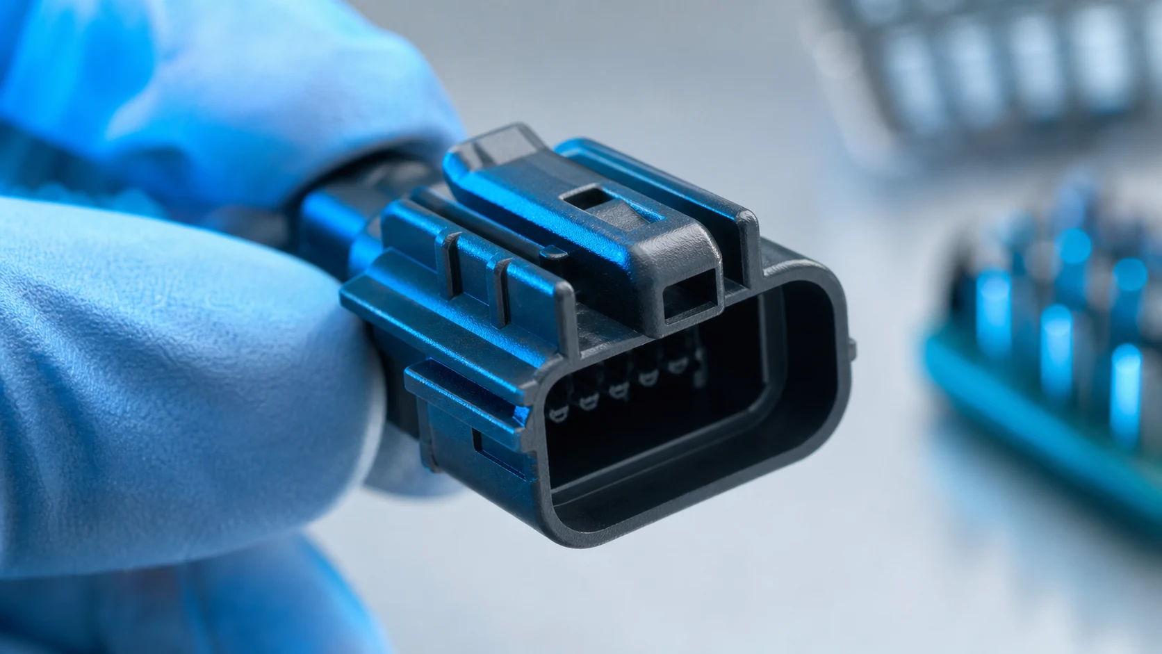
When a controls engineer in Manchester encountered intermittent shutdowns on a newly assembled industrial cabinet, she first changed the drive settings, then replaced a suspected power supply; the fault returned as soon as the enclosure warmed during a customer demonstration. The reversal came when the team compared the connector drawing, the crimp process, and the mating interface: the issue was a selection-and-assembly mismatch, not simply a bad part.
Summary: Custom Rectangular Power Connectors should be specified as a system—contacts, housing, wire, termination, mating half, panel, and validation plan. A useful electrical reality is that resistive heating follows I²R, so doubling current can produce four times the heat in the same resistance. Capture the real load profile, environment, and assembly process first; then review insulation and test evidence against the intended market and use, rather than selecting from a catalogue image alone.
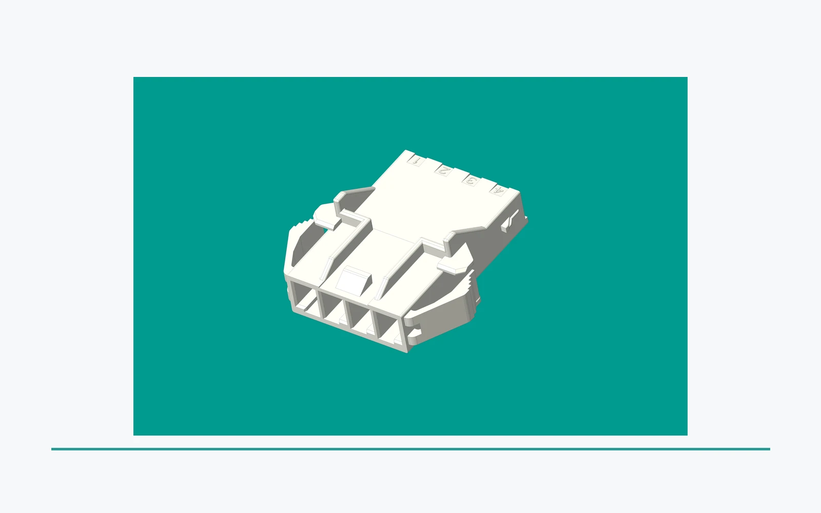
A custom connector project starts with the interface around the connector. Rectangular Power Connectors must be considered with the equipment architecture, service access, harness routing, operator actions, contamination exposure, and the documents that remain aligned through design changes. The goal is not a more elaborate part; it is a repeatable connection with evidence appropriate to the application.
Capture the requirement before choosing the interface
Turn the application into a controlled input list
Procurement and engineering should jointly record the mating cycles, peak and continuous load, conductor construction and gauge, ambient and self-heating conditions, vibration, ingress exposure, mounting method, servicing method, and destination markets. Include the mating connector and wire preparation in the requirement; an electrical power pin rectangular connector can only perform as consistently as the contact-to-conductor termination and the latch engagement allow. These are power-connector requirements, not optional details to fill in after the housing is selected.
Configuration needs to be unambiguous. Pin count, circuit assignment, polarization, keying, coding, cable exit direction, strain relief, and panel cut-out details belong on controlled drawings. The first article and the production work instruction should point to the same revision, otherwise a seemingly minor housing or terminal change can create a field-mating or serviceability problem.
Use keying to prevent the wrong decision at the point of use
Keying is a risk control, not decoration. Ask which similar-looking connectors must not mate, whether a connector can be inserted under poor visibility, and whether mixed-voltage or signal-and-power harnesses share an enclosure. Where a keying choice changes the connector family, document the rationale and verify it with representative mating trials rather than relying only on a 3D model.
Review current, temperature, voltage, and insulation together
Current review should use the actual duty cycle, not only a nominal label. Contact resistance, conductor resistance, number of loaded adjacent circuits, enclosure airflow, bundle density, and temperature at the termination all influence the temperature-rise result. Because heat loss and material limits are system-dependent, a current number copied from a different wire size, orientation, or loading pattern is weak evidence.
Voltage review is separate but connected. Define operating and transient conditions, circuit separation, insulation materials, clearance and creepage needs, pollution conditions, and any requirement for dielectric testing. The IEC 60512 series provides connector test methods; a qualification plan can select applicable methods for contact resistance, dielectric withstand, insulation resistance, temperature rise, vibration, and mechanical operation. A method is not a blanket approval, so the tested configuration and acceptance criteria must be traceable.
For an electrical power pin rectangular connector, the design review should also identify where power contacts sit relative to low-level circuits and exposed conductive hardware. In some applications, sequencing, shielding, separate cavities, or physical segregation may matter more than adding pins. The resulting drawing package should state those interface decisions explicitly.
Design pin count, keying, and termination for assembly
More positions do not automatically mean more flexibility. Reserve only the circuits with a defined purpose, group loads with thermal interaction in mind, and leave inspection access for every critical crimp or termination. If future options are likely, decide whether unused positions need cavity plugs, coding rules, or a separate variant; an undocumented spare position can become an unintended connection path. A 15-pin power connector is one example where the circuit map, rather than the count, must explain each reserved position.
Termination selection links electrical performance to factory capability. Crimp terminations require the correct terminal, wire range, strip length, applicator or hand tool, crimp-height window, pull-force process control, and visual criteria. Soldered or screw-based alternatives introduce their own heat, torque, flux, or maintenance controls. The appropriate choice is the one that can be assembled and verified consistently at the expected volume.
Run a pilot build with production-intent tools and operators. Inspect terminal retention, conductor brush, insulation support, seal or strain-relief engagement where relevant, latch operation, and mating force. Then record the approved wire and tooling combination. This closes a common gap: an interface that fits mechanically but cannot be made reliably on the intended line.
Validate the design and protect the documents
Validation should challenge the risks identified in the requirements review. Representative samples should be subjected to the selected IEC 60512 methods and any application-specific test plan, with the actual housing, contact finish, wire, seal, and loaded-circuit pattern recorded. Electrical checks before and after environmental or mechanical exposure help distinguish a robust interface from one that only passes an initial bench measurement.
Document control is part of technical performance. Maintain a revision-controlled specification, drawing, bill of materials, approved sample record, inspection plan, test report, and change-notification process. A single controlled part number cannot compensate for an uncontrolled substitution of plating, resin, wire, or crimp tooling. For recurring programs, agree in advance on the evidence required when a manufacturing change is proposed.
Compare custom interface paths by total cost
| Decision path | Best fit | Performance and compatibility | Unit-cost tendency | TCO and maintenance consideration |
|---|---|---|---|---|
| Standard catalogued interface | Stable requirements and proven mating geometry | Fastest route to known ecosystem limits | Usually lower development burden | Can add adaptation, harness, or service cost if the fit is poor |
| Configured family variant | Known family with changes to positions, keying, or exits | Balances compatibility with application-specific control | Depends on configuration and volume | Often reduces integration risk without a fully new interface |
| Purpose-designed interface | Distinct electrical, packaging, or error-proofing need | Can align contact layout and mechanics to the equipment | Includes non-recurring engineering and tooling | May lower field-error and assembly cost when the design is stable |
The comparison is not a price list. An illustrative total-cost calculation should include tooling amortization, qualification samples, inspection time, scrap exposure, rework, harness complexity, field-service access, and the consequence of an incorrect mate. A low component quotation can be outweighed by a recurring process or warranty risk.
Expose the cost drivers before committing tooling
| Cost driver or dimension | Questions to resolve | Commercial effect to assess |
|---|---|---|
| Contact system and wire | Which conductor, finish, loading pattern, and temperature condition apply? | Qualification scope, crimp tooling, yield, and material selection |
| Housing, keying, and latch | How will incorrect mating be prevented and service access retained? | Mould complexity, variant control, and potential field-error reduction |
| Tooling and validation | What samples, gauges, fixtures, and tests are needed? | Non-recurring cost, launch timing, and documentation workload |
| Annual volume and variant count | Is demand stable, and how many controlled configurations are required? | Amortization, inventory strategy, change-control burden, and supply continuity |
Buyers evaluating a rectangular power connector for sale should request a transparent separation between recurring piece cost and one-time development, tooling, validation, and change-management work. That distinction makes alternatives comparable without relying on unsupported price bands.
Apply standards and compliance claims precisely
IEC 61984 addresses safety requirements and tests for connectors within its defined scope; it does not remove the need to evaluate the finished equipment and its intended installation. The IEC 60512 series provides test methods for connectors, so a reference to it should identify the relevant method, sample configuration, and results rather than suggesting a universal product certification.
UL 1977 concerns component connectors for data, signal, control, and power applications. Component recognition or investigation, where applicable, is not the same as an approval of every assembly or end product. Market access decisions must account for destination market, intended use, installation conditions, and the precise marketing claim.
IATF 16949 is a quality-management-system scope for organizations in the automotive production and relevant service-parts supply chain; it is not a connector performance rating. Unsupported statements about standards, recognition, or certification can delay sourcing reviews and create compliance risk, particularly when a part is repurposed across markets.
Use a disciplined supplier-selection path
- Issue a requirement sheet that separates mandatory interface constraints from preferred options.
- Request drawings, material and termination information, applicable test evidence, and revision status for the proposed configuration.
- Build and test representative harnesses with the production-intent wire, tooling, and mating half.
- Agree on first-article approval, ongoing inspection, and engineering-change communication before release.
For teams comparing configurable families, ZUCH offers rectangular connector options alongside its broader connector portfolio. Its stated qualifications—an IATF 16949:2016 quality system, a CNAS-recognized laboratory, and a UL Witness Lab—should be reviewed against the exact project scope and requested evidence, rather than treated as a substitute for application validation.
Which inputs should be fixed before custom tooling is approved?
A tooling decision is stronger when the requirement sheet separates mandatory geometry from preferred features.
| Review point | Record or question | Why it closes risk |
|---|---|---|
| Need | Circuit map, load, envelope, keying, mounting and service constraint | Shows why a catalogue option cannot close the requirement |
| Tooling | Mold/insert scope, tolerances, material and ownership | Defines the non-recurring and change-control exposure |
| Validation | Mating, electrical, thermal, environmental and process evidence | Prevents a cosmetic prototype from becoming a release |
| Commercial | Forecast, amortization, spares, revision and supply plan | Connects tooling to total cost and continuity |
FAQ: When should a custom rectangular power connector be tooled?
How do I choose pin count for a custom power connector?
Start with a circuit list, then group contacts by current, voltage separation, thermal interaction, and service needs. Add positions only when their function and protection method are controlled; unused cavities may need explicit treatment in the drawing and assembly instructions.
What should an electrical power pin rectangular connector specification include?
It should identify the mating interface, terminals, wire, loading conditions, keying, housing orientation, retention features, environmental conditions, and required validation evidence. The same specification should identify the governing revision and any approved substitutions.
Is a rectangular power connector for sale suitable for an OEM program?
It may be, provided its configuration, supply controls, validation evidence, and assembly process match the OEM requirement. A rectangular power connector for sale should be assessed by its exact tested construction, not by assuming a listed family covers every wire, contact, or keying combination.
Which tests matter before release?
Select tests from the risk profile, often including electrical continuity or resistance, insulation-related checks, temperature rise, retention, mating operation, vibration, and thermal exposure. IEC 60512 can inform method selection, while the application determines the sample condition and acceptance criteria.
When is custom tooling economically justified?
It is worth assessing when a stable program can offset tooling and validation through simpler assembly, fewer variants, improved service access, or reduced incorrect-mating exposure. Evaluate the full program lifecycle, not only the first piece-cost quotation.
How should a custom program reserve positions?
Start with the circuit list and loading pattern, then reserve positions only when the controlled architecture needs them. Do not use a high count as a proxy for capacity.
What evidence supports a custom tooling business case?
Model stable requirements, credible volume, NRE, validation effort, revision exposure and supply continuity together before approving the investment.
What should a custom power-connector drawing include?
Include the mating interface, keying, contacts, wire and terminal system, mounting, cable exit, environment, electrical limits, inspection and revision control.
Can a rectangular connector listing be used directly in an OEM program?
It may be a candidate, but the OEM must verify configuration, supply controls, application evidence and release requirements rather than relying on a listing.
Which tests matter before custom release?
Select tests from the risk profile and detail specification, covering the actual electrical, mechanical, environmental and process boundaries; no universal test set is implied.
How should an alternate custom design be controlled?
Freeze drawings, approved materials, tooling changes, mating parts, inspection and validation triggers so an apparently small revision does not bypass qualification.
References
- IEC 61984: Connectors — Safety requirements and tests — public scope checked 2026-10-14; it does not establish a product-specific rating, certification or application approval.
- IEC 60512-1:2018 — Connectors: tests and measurements — public scope checked 2026-10-14; it does not establish a product-specific rating, certification or application approval.
- IEC 60664-1 consolidated publication — Insulation coordination — public scope checked 2026-10-14; it does not establish a product-specific rating, certification or application approval.
- Global Electronics Association IPC standards revision table — public scope checked 2026-10-14; it does not establish a product-specific rating, certification or application approval.
Conclusion
Custom rectangular power connectors make sense when a stable application requirement cannot be met by a controlled catalogue interface and the full cost of customization is understood. Freeze the circuit map, load, envelope, keying, mounting, cable route and service conditions before approving tooling. Then define tooling ownership, materials, inspection, validation, revision triggers, forecast, spares and supply continuity. IEC 61984 and IEC 60512 provide connector safety and test-planning context; they do not turn a prototype or supplier statement into an application approval. ZUCH's rectangular connector range can be compared with a custom path against the requirement sheet, while the OEM remains responsible for the business case, qualification and release decision.