Zhejiang ZUCH Technology Co., Ltd.
When a controls engineer in Detroit encountered repeated heat marks on an appliance prototype during final assembly, she first replaced the suspect part, then watched the same symptom return after the next harness was mated. The visible failure appeared quickly, but the reversal was more useful: the root cause was not simply a bad connector; it was a selection and specification review that had treated a familiar 15-position appearance as proof of system fit.
Summary: A 15-pin layout is an input to a design review, not a universal interface definition. The recommended action is to confirm the interface family, circuit assignment, mating geometry, test evidence, and intended-use approvals before releasing a drawing. SATA specifications are administered by SATA-IO, while appliance and vehicle harnesses can have entirely different mating, environmental, and quality requirements even when their housings look broadly similar. A pin count of 15 cannot establish interchangeability.
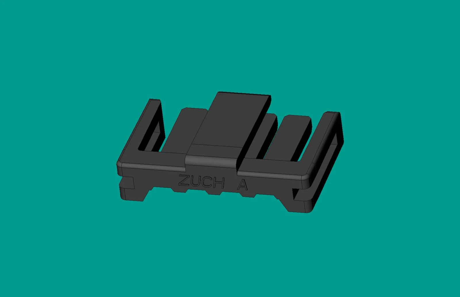
Why can a familiar 15-position label mislead a design review?
Procurement teams often begin with search language, while engineering teams must end with a controlled interface. The familiar SATA power form is a 15-contact interface used within its own ecosystem; SATA-IO maintains information for that ecosystem. That fact does not turn every 15-position housing into a substitute for a PC interface, nor does it define an appliance or automotive harness.
A 15 pin power connector may therefore describe a count, a buyer’s search term, or a particular interface family. A multi-pin power connector is similarly broad: it may carry power, distribute several circuits, provide signal paths, or combine functions. Before evaluating a catalog image, a team should identify the mating half, polarization, contact system, wire range, terminal retention, circuit map, service condition, and destination market. General connector families can be compared through a product-category starting point such as connector systems, but the approved drawing remains the controlling document.
What does a 15-pin layout specify, and what remains unknown?
Why is position count only the first field in the drawing?
Fifteen positions tell a reviewer how many locations may exist; they do not tell the reviewer which locations are populated, their circuit roles, contact resistance limits, permissible temperature rise, or mating sequence. A useful request for quotation starts with a numbered circuit table and a drawing revision, then links each circuit to conductor size, expected load profile, and required evidence. IEC publishes connector work through the International Electrotechnical Commission; its documents should be selected for the actual product and use case rather than inferred from the position count. A power connector is defined by the complete electrical and mechanical interface, not the number of positions alone.
Why does electrical fit require a load case rather than a label?
A circuit label alone cannot establish current-carrying suitability. Reviewers should record continuous and peak current, duty cycle, ambient temperature, conductor termination, number of loaded adjacent circuits, and allowable temperature rise. IEC 60512 is a connector test-method series, so it can help structure measurements such as contact resistance or current-carrying assessment; it is not, by itself, a blanket product certification. For every one of the 15 positions, the question is whether the documented configuration passes the relevant test plan under the intended load and enclosure conditions.
Which mechanical and assembly variables decide whether the interface will work?
Interchangeability is usually lost in details that a front-view image hides: keying, latch engagement, terminal design, terminal-position assurance, panel clearance, strain relief, and the direction of harness exit. A rectangular power connector may share an outline with another part yet fail to mate, fail to lock, or create unacceptable insertion force. The drawing should define critical dimensions and permissible variation in millimetres, rather than relying on a nominal family name.
Assembly also changes the connector’s effective performance. Crimp tooling, strip length, insertion depth, pull-force verification, and operator access should be captured in a process plan. IEC 60512 provides named mechanical and environmental test methods that can be cited in a validation plan, but the buyer still needs to agree the sample condition, sequence, acceptance criteria, and whether tests are performed on a finished harness. This is where mating geometry turns from a CAD concern into a field-reliability concern.
How does lifecycle cost change the connector decision?
Unit price is visible at quotation; an engineering change order, production hold, harness rework, or return is not. An illustrative comparison is simple: if one unclear mating requirement creates one containment event across a production launch, the cost can outweigh a modest component saving even before expedited freight or requalification is considered. The calculation is illustrative, not a price forecast; it is intended to make documentation, validation, and service access visible in the total-cost decision. The same documentation risk applies when selecting an 8-pin power connector; reducing the position count does not remove it.
Component-recognition claims also carry commercial consequences. UL 1977 addresses component connectors for use in data, signal, control, and power applications. Recognition of a component does not automatically approve every finished appliance, vehicle, cable assembly, or market claim. Procurement should obtain the relevant file, configuration, and conditions of acceptability before describing the completed system as compliant.
Why can similar-looking 15-position interfaces require different decisions?
| Review dimension | PC SATA power context | Appliance harness context | Automotive harness context |
|---|---|---|---|
| Interface basis | SATA ecosystem documentation and the exact mating design | Equipment drawing, appliance construction, and harness routing | Vehicle program drawing, system environment, and OEM requirements |
| Compatibility question | Does the mating interface match the specified SATA application? | Does the housing, terminal, wire, and enclosure arrangement match? | Does the approved connector-and-harness configuration match the vehicle program? |
| Durability evidence | Use the applicable interface and test requirements | Review cycles, loads, heat, vibration, and service access for the equipment | Review vibration, temperature exposure, fluids, sealing, and retention as specified |
| Unit-cost tendency | Often influenced by ecosystem volume and exact configuration | Driven by terminals, tooling, assembly steps, and documentation | Driven by validation scope, traceability, process control, and program requirements |
| TCO risk | Wrong mating assumption or configuration control | Assembly error, rework, thermal issue, or service difficulty | Program nonconformance, validation delay, or field containment |
The table is a decision framework, not a claim that all SATA, appliance, or automotive connectors share one approval path. A second search for a 15 pin power connector should therefore begin with the application column, then move to the controlled part number and test evidence.
Which application details should travel with the 15-position RFQ?
| Application | Dimensions and constraints to document | Useful validation focus | Commercial review point |
|---|---|---|---|
| PC or storage equipment | Mating interface, orientation, circuit map, cable exit, space envelope | Specified interface fit and relevant electrical test evidence | Confirm the exact ecosystem interface; do not infer it from 15 positions |
| Appliance power distribution | Wire size, terminal style, latch access, heat sources, panel or chassis clearance | Finished-harness retention, temperature rise, and assembly-process checks | Include tooling, inspection, and serviceability in the quotation comparison |
| Automotive subsystem | Keying, CPA/TPA needs where specified, sealing, routing, vibration exposure | Program-defined environmental, retention, and traceability checks | Align validation evidence with the customer’s program and release process |
Which standards apply, and what do they actually prove?
Four names are frequently compressed into a single “certified connector” statement, which creates avoidable risk. IEC 61984 covers safety requirements and tests for connectors within its stated scope; it is not a substitute for checking whether a particular product, installation, or end equipment is covered. IEC 60512 provides test methods for electromechanical components, so a report should name the applicable method and conditions rather than present the series as a product approval.
UL 1977 is a component-connector standard and its recognition must be read with its applicable categories and conditions. IATF 16949, meanwhile, is a quality-management-system standard for the automotive supply chain, not an approval of an individual connector’s electrical or environmental performance. Official IATF 16949 information is useful for separating quality-system scope from product validation. Destination market, intended use, customer specification, and every marketing claim determine what evidence is required.
What selection sequence should procurement and engineering follow?
- Freeze the mating interface with a controlled drawing, part-number revision, and circuit map before comparing alternatives.
- For a multi-pin power connector, convert the electrical load case into documented acceptance criteria, including ambient conditions and adjacent loaded circuits.
- Review the connector, terminal, wire, seal or strain relief, and crimp process as one harness system.
- Request a traceable evidence package: drawings, material or approval information where applicable, test reports, and stated conditions of acceptability.
- Plan pilot assembly and service-access checks before a production release; correct a fit issue while changes are still inexpensive.
For projects that need configurable harness-facing options, ZUCH can be evaluated from module 7 onward as a connector-system manufacturer with rectangular connector families. Its stated IATF 16949:2016 quality-system qualification, CNAS-recognized laboratory, and UL Witness Lab should be matched to the buyer’s specific drawing, test plan, and approval needs; none should be read as automatic approval for a PC SATA application. Teams comparing a rectangular connector family can use those documents as part of a supplier evidence review.
How should a 15-position interface be screened before an alternate is approved?
Screen the candidate in the same order a design review would: identify the exact ecosystem or equipment, compare the mating drawing and connector-face orientation, and map every populated, intentionally empty and blocked position. Then match each circuit to its terminal, conductor, insulation, seal or strain-relief condition and load case. A 15-position housing can be mechanically similar to another part while using different contact sizes, keying, pitch or retention.
- Ask for the controlled documents. Require the housing and mating part numbers, revision, circuit map and assembly instructions.
- Check electrical fit. Review current, voltage, duty cycle, adjacent loaded circuits and temperature conditions for the actual configuration.
- Check production fit. Confirm terminal insertion, crimp or solder process, retention, service access and change-control responsibilities.
- Approve by evidence. Record the sample build, selected test methods, acceptance criteria and any application-specific restrictions.
This process prevents a marketplace description such as “15-pin power connector” from becoming an uncontrolled substitute decision.
Which application fields must accompany a 15-position connector request?
The same count can support different interfaces; the application fields determine which evidence is relevant.
| Review point | Record or question | Why it closes risk |
|---|---|---|
| Equipment ecosystem | PC/storage, appliance or vehicle system and exact mating part | Prevents a generic count from being treated as a named standard |
| Circuit and load | Pin map, return path, current profile and temperature | Links the contacts to the real electrical duty |
| Mechanical | Keying, orientation, latch, mounting and cable exit | Controls fit and service access |
| Program evidence | Environment, validation plan, traceability and release owner | Makes an alternate auditable |
FAQ: What does a 15-position label fail to identify?
Are all 15-pin power connectors SATA connectors?
No. A 15-pin count alone does not define the SATA interface, the mating geometry, or the circuit assignment. Confirm the mating drawing and intended ecosystem before specifying the part.
What should a multi-pin power connector RFQ include?
Include the controlled part drawing, circuit map, wire range, load profile, environmental conditions, validation requirements, annual volume, and packaging or traceability needs. If the assembly is serviceable, add access and replacement requirements before tooling is selected.
Can an appliance connector be used in an automotive harness?
Only when the complete intended-use requirements and customer release process support it. Similar pin counts or housings do not demonstrate performance under vehicle-specific routing, vibration, temperature, sealing, or quality controls.
How do buyers evaluate a rectangular power connector beyond price?
Compare the complete system: mating control, terminals, wire processing, validation evidence, documentation, service access, lead time, and cost of change. Related families such as RAST connectors may help narrow an appliance-oriented discussion, but only the applicable drawing and evidence establish fit.
What is the first question to ask about a 15 pin power connector?
Ask, “What exact mating interface and application does this part number serve?” The answer should lead to a drawing, circuit assignment, and verification plan—not merely a marketplace label or a front-view photograph.
What is a 15-pin connector used for?
It may be used in a specific computer, appliance or harness ecosystem, but the number alone does not identify the function. For example, a 15-pin SATA power interface belongs to a defined storage-device ecosystem; a different 15-position housing may serve another application. Confirm the mating drawing, pin assignment and intended equipment before treating the connector as a replacement.
Can a different 15-position interface also be a SATA connector?
No. SATA is a defined ecosystem with its own geometry and circuit assignment; position count alone does not establish SATA compatibility.
Can an appliance connector be reused in an automotive harness?
Only after the complete application, environmental, process and customer-release requirements are reviewed for the intended harness.
What should a 15-pin RFQ include?
Include the mating part, controlled drawing, pin map, wire and terminal details, load profile, temperature, environment, tooling and validation records.
Why does a pin map matter more than a product photo?
The pin map connects each position to the circuit function and polarity; a photo cannot prove the unseen contact, keying or termination configuration.
How should an alternate 15-position interface be screened?
Compare identity, geometry, circuit assignment, contacts, wire, environment, process and evidence in the same review sequence before sampling.
Does a higher position count mean higher power capacity?
No. Capacity depends on the complete contact and thermal design, loading pattern, conductor and specified conditions, not position count alone.
References
- IEC 61984: Connectors — Safety requirements and tests — public scope checked 2026-10-14; it does not establish a product-specific rating, certification or application approval.
- IEC 60512-1:2018 — Connectors: tests and measurements — public scope checked 2026-10-14; it does not establish a product-specific rating, certification or application approval.
- IEC 60664-1 consolidated publication — Insulation coordination — public scope checked 2026-10-14; it does not establish a product-specific rating, certification or application approval.
- Global Electronics Association IPC standards revision table — public scope checked 2026-10-14; it does not establish a product-specific rating, certification or application approval.
Conclusion
A 15-position connector should be identified by its complete mating and application system, not by the number in a marketplace title. Confirm the equipment ecosystem, housing and mate, keying, circuit map, contact and wire system, current and temperature duty, environment, service route and program release owner. This sequence prevents a SATA, appliance or automotive assumption from entering the drawing without evidence. IEC 61984 and IEC 60512 provide general connector safety and measurement context, while IEC 60664 addresses insulation coordination within its declared scope; none proves a cross-application substitute. ZUCH can review a documented multi-pin interface inquiry, but suitability remains tied to the intended equipment and controlled validation record.