Zhejiang ZUCH Technology Co., Ltd.
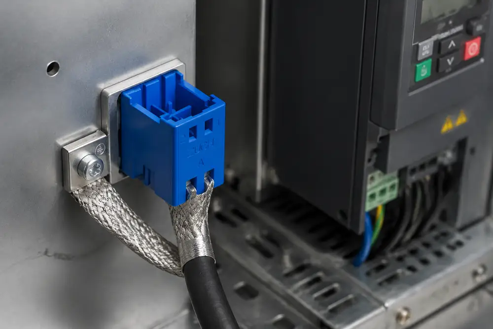
When an automation engineer in Eindhoven traced intermittent encoder faults at an industrial packaging line, the failures appeared during VFD switching: position feedback dropped out, the drive stopped, and production paused. The connector was initially blamed, but the reversal came after inspection showed a pigtail shield termination and a discontinuous return path at the cabinet entry. Cable-shield termination and return-path design—not merely a bad connector—were allowing switching noise to couple into the signal circuit.
Summary: Effective connector shielding is a system property. Use a low-impedance, preferably 360-degree shield termination where the cable enters a conductive enclosure; preserve bonding continuity through the connector interface; and verify the assembly in its installed configuration. IEC 61000-4-6 addresses conducted RF immunity, while connector test standards assess components rather than certifying an entire machine. Start by mapping the noise source, victim circuit, coupling path, and return path before selecting hardware.
For a related technical topic, see Why Rectangular Connectors Are Popular in Robotics?.
How EMI reaches a rectangular connector
Electromagnetic interference (EMI) is unwanted energy that disrupts a circuit’s intended operation. Fast switching edges from drives, servo amplifiers, contactors, and power supplies create conducted and radiated noise. A cable can become both an antenna and a route for common-mode current, especially when its screen is interrupted at the enclosure boundary.
Rectangular Connectors are often selected because one interface can carry power, control, and signal contacts in a compact, serviceable format. That convenience also means the design team must separate sensitive circuits from noisy circuits, define shell-to-shell bonding, and understand what each insert, housing, hood, clamp, and panel cutout contributes. A conductive housing alone cannot compensate for an open seam, a painted mounting surface, or a shield that stops short of the entry point.
At high frequency, impedance—not DC resistance alone—governs a return path. A long, narrow conductor adds inductance, so a short, broad metal-to-metal bond is usually more useful than a long drain-wire “pigtail.” The commonly specified 360-degree termination describes circumferential contact between the cable screen and a conductive clamp or gland; it reduces the exposed transition where common-mode energy can radiate or couple inward. The exact outcome still depends on cable construction, frequency content, enclosure bonding, and installation geometry.
Diagnosis should distinguish the source, coupling mechanism, and susceptible victim. IEC 61000-4-6 is an equipment-level conducted-immunity test method; it does not prove that one connector will solve a field issue. Continuity checks, clamp inspection, and controlled cable-routing changes help reveal the dominant path.
Shield termination, grounding, and enclosure continuity
Shielding and grounding are related but different. A cable screen intercepts interference and provides a path for induced current; grounding or protective bonding connects exposed conductive parts to a reference and, where required, to protective earth. The useful question is not whether a shield is “grounded” in the abstract, but whether its termination creates an intentional low-impedance RF path at the enclosure boundary without creating a safety or signal-reference error elsewhere.
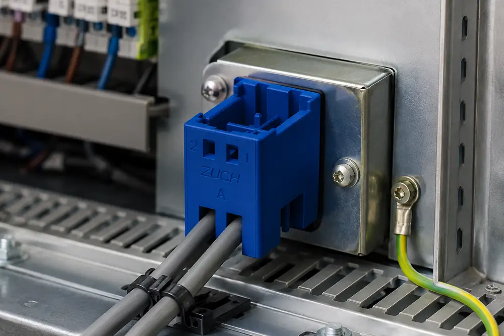
For a shielded signal cable, terminate the braid or foil as close as practical to the connector’s conductive entry hardware. Use a clamp or backshell that makes broad, repeatable contact with the screen, and ensure the connector hood, panel hardware, and enclosure have conductive contact where the design calls for it. Do not assume a mounting screw through paint provides a reliable high-frequency bond. A protective-earth conductor must still be sized and connected according to the applicable equipment requirements; a cable screen is not automatically a substitute for it.
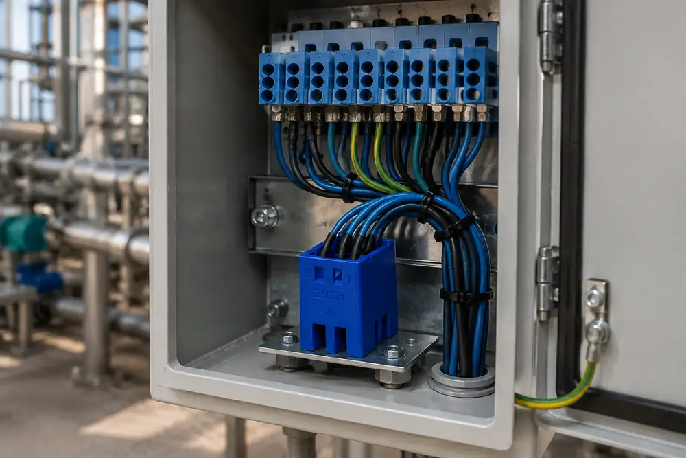
A rectangular power connector merits extra care when power and low-level signals share an enclosure. Keep high-current or fast-switched conductors physically separated from encoder, analog, communication, or sensor circuits; respect the connector manufacturer’s segregation and creepage/clearance guidance; and route cable screens to the chosen enclosure boundary rather than across an unplanned internal path. A locking system matters as well because vibration can affect the mechanical integrity of the interface; compare relevant approaches in this guide to rectangular connector locking mechanisms.
| Design choice | EMI implication | What to inspect | TCO consideration |
|---|---|---|---|
| 360-degree shield clamp | Creates a broad enclosure-boundary termination | Screen coverage, clamp contact, strain relief | May reduce troubleshooting and unplanned rework when installation is repeatable |
| Drain-wire pigtail | Adds a longer inductive transition at higher frequencies | Length, routing, and connection point | Simple assembly can shift cost to EMC investigation if it is unsuitable for the noise spectrum |
| Conductive hood and bonded panel | Can continue the shielding path across the interface | Finish removal where specified, gasket/seam condition, fastener torque | Maintenance procedures must preserve the intended contact surfaces |
| Nonconductive or isolated interface | May interrupt shell bonding unless another designed path exists | Bond straps, panel transition, documented return path | Useful only when isolation is intentional and validated for the application |
The cost of an EMI decision is rarely just the connector bill of materials. Poorly documented termination can drive commissioning delay, rework, and intermittent returns; costly features without an installation method may add no system benefit. Control mating hardware, cable preparation, instructions, and testing as one assembly.
Design and diagnose the whole cable-to-enclosure path
The practical boundary runs from noise source through cable and connector to the enclosure and affected circuit. Identify every shield, shell, protective-bond conductor, signal reference, panel opening, and mixed-voltage interface. Decide whether to bond the screen at one or both ends from the noise type, architecture, safety design, and EMC plan—not a copied rule.
Recreate the symptom, then change one controlled variable at a time. Appropriate oscilloscope probes can examine transients; a current probe can help locate shield or bond currents; and equipment-level immunity testing checks a corrective design. Record routing, grounding points, orientation, and panel contact conditions so the fix is repeatable.
| Observed condition | Likely path to investigate | Design or diagnostic action | Evidence to retain |
|---|---|---|---|
| Fault coincides with drive switching | Common-mode current or capacitive coupling | Inspect screen termination and source-to-enclosure bonding; separate affected routing | Time-correlated waveform and installation photos |
| Issue changes when hood is touched or fastened | Discontinuous shell or panel bond | Check conductive contact surfaces, fastener sequence, and continuity | Bond-resistance method and assembly record |
| Only one cable build fails | Screen coverage, clamp process, or termination geometry | Compare cable preparation and strain relief against the approved work instruction | Sample inspection and controlled comparison result |
| Lab result differs from installed machine | Enclosure, routing, or return path not represented | Test the complete representative assembly and document configuration | Test setup, cable layout, and configuration revision |
modular rectangular connectors can help teams separate functions, service individual modules, and configure mixed interfaces. The electrical benefit is not automatic: module allocation should preserve physical separation, contact ratings, and the intended shield/return-path architecture. For an overview of this format, see modular rectangular connectors; for broader format choices, consult the guide to rectangular connector types.
Standards, compliance, and a defensible selection process
Standards must be read for scope. The IEC 60512 connector test series contains defined test methods for electromechanical connector characteristics; an individual result under a connector test method is not a certification of the completed machine’s electromagnetic compatibility. IEC 61000 standards address EMC phenomena, test environments, and immunity or emission methods at the equipment or system level. IEC publication information and standards listings are appropriate starting points for confirming the current edition and the applicable part.
UL 1977 concerns component connectors within its defined scope; it does not make an assembled cable and enclosure EMC-approved. USCAR-2 may apply when an automotive customer specifies it, not as a universal industrial rule. Destination market, equipment category, customer requirements, and sales claims determine the evidence needed. Unsupported “EMI certified” language can create qualification and commercial risk.
Use the following procurement actions to turn intent into a controlled requirement:
- Describe the noise sources, susceptible circuits, cable routes, enclosure transitions, and expected installation environment.
- Specify the cable screen construction and the required termination method, including whether the hood, clamp, panel, and enclosure must form a bonded path.
- Request drawings, material/finish information, assembly instructions, and the test evidence relevant to the customer’s stated requirement; do not infer broader performance from a single document.
- Validate a representative cable-and-enclosure assembly using the applicable equipment-level EMC plan, then freeze the installation details in manufacturing documentation.
For teams evaluating configurable interfaces, ZUCH can be considered as a sourcing partner for connector configurations and supporting technical documentation. The useful conversation is a requirements review—contact allocation, cable diameter, hood style, locking, panel interface, and the customer’s validation plan—rather than an assumption that one shell feature guarantees system EMI performance.
Frequently asked questions
What is EMI shielding in a rectangular connector?
It is the use of conductive connector hardware and a controlled cable-screen termination to limit unwanted electromagnetic coupling at the interface. Its performance depends on the complete path through the cable, hood, panel, enclosure, and installation, not just the connector housing.
Why do industrial connectors need EMI shielding?
Industrial machinery often places drives, power conversion, sensors, communications, and control electronics in close proximity. Shielding helps manage coupling paths that could disrupt signals, but the level of protection required must be based on the actual noise environment and equipment EMC plan.
How is cable shielding terminated at a connector?
Prepare the cable screen according to the approved work instruction and clamp it with broad conductive contact near the connector entry. Avoid treating a long drain-wire lead as equivalent to a 360-degree termination; verify the selected method against cable size, hardware, and the application’s frequency range.
Can a metal connector housing improve EMI performance?
Yes, a conductive housing can support continuity between a cable screen and an enclosure when the mating surfaces and panel bond are designed correctly. It cannot compensate for an unbonded panel, poor screen clamp, discontinuous seam, or an inappropriate cable architecture.
What is the difference between EMI shielding and grounding?
Shielding manages interference coupling by enclosing or providing a path for unwanted electromagnetic energy. Grounding and protective bonding establish electrical references and safety connections; their relationship to a cable screen must be designed rather than assumed.
How do I test whether connector shielding is working?
First inspect the physical termination and shell-to-enclosure continuity, then test a representative installed assembly under the disturbances relevant to the equipment. Use appropriate diagnostic tools and the applicable equipment-level EMC test plan; component test data alone cannot establish system immunity.
References and next step
- International Electrotechnical Commission: standards information
- IEC Webstore: connector-related publication information
- SAE International: USCAR-2
The durable judgment is simple: a connector shield is only as effective as the continuous, intentional path it completes.
When your team is ready to align interface selection with cable, enclosure, and validation requirements, explore ZUCH connector products and contact the team with your application details.