Zhejiang ZUCH Technology Co., Ltd.
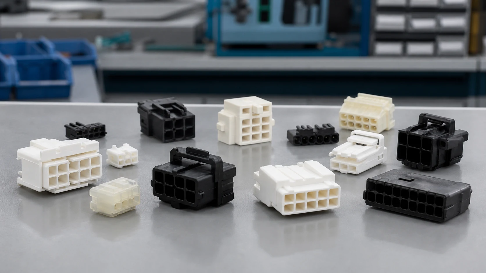
When a controls engineer in Stuttgart encountered intermittent signals on a packaging-line retrofit, she replaced a visibly worn mating pair and ran a 16-channel continuity check. The line failed again as soon as the cabinet door moved; the reversal came when the team compared the drawing, pitch, terminal retention, and panel cutout. The root cause was not simply a bad product, but an underspecified interface: a board-level header had been treated as a field-serviceable panel connection.
Summary: Rectangular connectors are selected first by interface—board-to-board, wire-to-board, or panel-mounted—then by circuit count, pin pitch, termination, retention, environmental exposure, and the applicable test evidence. IEC 61984 addresses safety requirements and tests for connectors within its defined scope, while IEC 60512 is a test-method series rather than a product certificate. For buyers of rectangular electrical connectors, the practical action is to freeze the mating family and mechanical envelope before comparing suppliers; a matching pin count alone does not establish interchangeability.
The rectangular form factor supports dense, repeatable multi-circuit interfaces in appliances, controls, transport equipment, and industrial electronics. Catalog descriptions of rectangular electrical connectors are a useful starting point, but the shape is not a universal mating standard. Keying, pitch, contact geometry, polarization, latching, plating, housing material, and terminal design determine whether two parts can mate and perform as intended. This distinction matters because a low unit price can be outweighed by field rework, assembly errors, qualification time, or a late enclosure change.
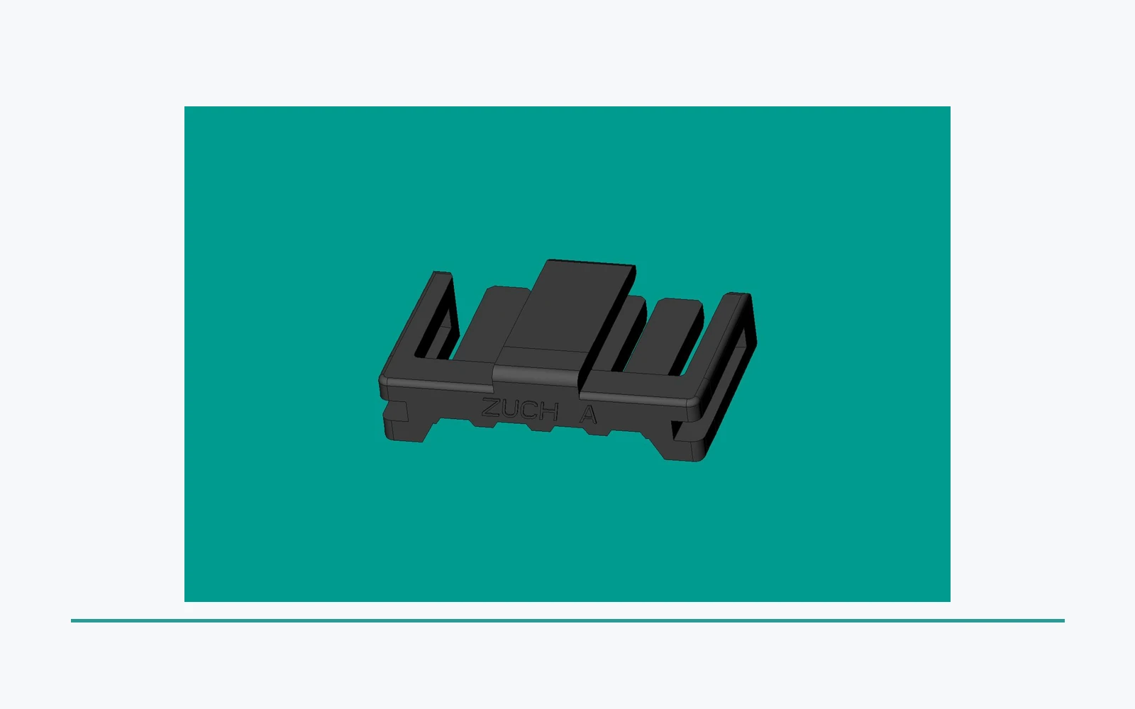
Rectangular Connectors: board-to-board families and their limits
This category covers multiple board-level mating systems, including headers, receptacles, sockets, mezzanine pairs, and shrouded headers. Board-to-board systems join two printed circuit assemblies directly. Common nominal pitches range from 0.5 mm in dense electronic assemblies to 2.54 mm in larger through-hole systems; the usable circuit count depends on rows, keying, creepage requirements, and available board real estate. A 20-position part at one pitch is therefore not a substitute for a 20-position part at another pitch. If the board interface is a power connector, add the electrical duty to the geometry review. A custom rectangular power connector still needs the same checks rather than an assumed fit.
Headers, sockets, and mezzanine pairs
Pin headers and sockets suit parallel or perpendicular board relationships where service access and cost are important. Mezzanine pairs support close board stacking, but their stack height, coplanarity tolerance, guiding features, and mating sequence must be designed as a pair. IEC 60512 test methods can be used to evaluate connector measurements and mechanical operation; they do not make separately sourced headers and receptacles generically compatible.
For a controller, a PCB header should be specified with its mating receptacle family, number of rows, contact loading, mounting style, and any orientation key. Engineering teams should treat these interfaces as family-specific, even where external dimensions look similar. Specification drawings should also state the allowed insertion direction and board-side clearance. These details prevent a layout team from choosing a footprint that accepts a component mechanically but cannot meet the intended mating or assembly process.
Wire-to-board and panel-mount interfaces solve different installation problems
Wire-to-board connectors combine a board-mounted header with a crimp, insulation-displacement, or soldered wire-side terminal in a housing. They are useful when harness assembly occurs away from the PCB and when a latch must resist handling loads. Two circuits may be adequate for a sensor, while 12, 16, or more circuits can consolidate a control harness; circuit count alone still says nothing about wire range, terminal type, or latch geometry.
Housing and terminal options
Housings can be unshrouded or shrouded, single- or dual-row, polarized, keyed, latched, flange-mounted, or sealed as part of a system. Terminal options include stamped-and-formed crimp contacts, receptacle contacts, tabs, and solder tails; the selected wire size, insulation diameter, crimp tooling, plating, and retention feature must be evaluated together. IEC 60512 includes test methods for characteristics such as contact resistance and mechanical operation, providing a common way to define evidence rather than a shortcut around application validation.
Panel mounting is an enclosure decision
Panel-mounted rectangular interfaces place the disconnect point at an enclosure wall, cover, or machine frame. They may use snap-in lances, screws, nuts, flanges, gaskets, backshells, or strain-relief arrangements. The right choice depends on panel thickness, cutout tolerance, access side, cable bend radius, service cycle, and sealing path. A connector rectangular in outline may have no compatible cutout, locking feature, or wire-side mate with another rectangular family.
| Interface | Best fit | Efficiency and serviceability | Compatibility control | Unit-cost tendency and TCO consideration |
|---|---|---|---|---|
| Board-to-board | Compact PCB assemblies | Few harness steps; board alignment is critical | Match pitch, stack height, keys, and contact system | Often efficient in assembly; layout changes can be costly |
| Wire-to-board | Harness-to-PCB connections | Supports modular assembly and replacement | Match terminal, housing, wire range, and latch | Harness labor and crimp verification affect TCO |
| Panel-mounted | Enclosures and service disconnects | Accessible interface; adds cutout and strain-relief work | Match panel thickness, cutout, mate, and sealing path | Higher hardware effort may reduce field-service time |
Choose pin count and pitch from the complete connection system
Pin count starts with present circuits, dedicated protective or reference positions where required, and a realistic allowance for future variants. Pitch sets center-to-center contact spacing; common catalog increments such as 0.5 mm, 1.0 mm, 2.0 mm, and 2.54 mm illustrate the density-versus-handling trade-off, not a universal performance ranking. Smaller pitch can raise density, while larger pitch can simplify harness handling and provide more mechanical separation.
A connector rectangular callout should expand into a controlled requirement: family and mating part number, positions and populated positions, row configuration, pitch, gender/contact interface, keying, termination, mounting, materials, target environment, and required test plan. If a design uses high-current, mains-related, automotive, or safety-relevant circuits, engineering must confirm spacing, temperature, derating, and regional requirements from the applicable product documentation rather than infer them from the outline.
| Application | Useful starting architecture | Primary dimensions to review | Evidence to request |
|---|---|---|---|
| Compact control PCB | Board-to-board header/socket or mezzanine pair | Pitch, stack height, PCB footprint, coplanarity | Drawing, mating-cycle method, contact-resistance test results |
| Appliance wire harness | Wire-to-board housing and crimp terminal | Wire range, terminal retention, polarization, assembly tooling | Crimp process data and IEC 60512-relevant test evidence |
| Machine cabinet | Panel-mount housing with strain relief | Cutout, panel thickness, latch or fastener, service access | Mounting drawing and mechanical-operation test plan |
| Wet or dusty equipment | System designed with seals and protected cable exit | Ingress path, gasket compression, mating condition, maintenance | Application-specific sealing and environmental test evidence |
Illustrative TCO logic is straightforward: if a 24-circuit harness takes 10 additional seconds to orient, terminate, and inspect because its keying is unclear, that labor repeats at every build and can exceed a small component saving. The calculation must use the buyer’s actual labor rate, yield, rework frequency, and service exposure. The best architecture is the one that reduces the total risk of wrong mating, poor termination, and inaccessible maintenance—not the one that looks most interchangeable in a catalog photograph.
Standards, test methods, and compliance claims
IEC 61984, Connectors—Safety requirements and tests, establishes safety requirements and associated tests for connectors within its stated scope. It should be used by checking the current edition, rated conditions, intended equipment, and exclusions against the actual design. It does not mean every item called a rectangular connector has the same ratings, approval status, or suitable use.
IEC 60512 is a series covering tests and measurements for connectors. It is valuable when a specification needs a named method for contact resistance, mechanical operation, or environmental behaviour, but it is a test-method framework, not a certificate that automatically proves a complete product or assembly is compliant. For rectangular electrical connectors, unsupported statements about compliance can create tender risk, shipment delays, and warranty disputes; destination market and end-use rules still govern what evidence is needed.
A procurement checklist before the first purchase order
- Lock the mating interface by manufacturer family and drawing; do not approve alternatives solely by position count or outline.
- Document pitch, populated circuits, keying, panel or PCB geometry, termination method, wire details, and assembly tooling.
- Request drawings plus application-relevant IEC 60512 test evidence, and define any additional vibration, temperature, sealing, or retention tests needed for the product.
- Qualify the complete mated assembly in its enclosure and harness, then manage changes to terminals, plating, resin, and tooling through a controlled process.
For buyers needing a configurable supplier discussion, ZUCH is a Chinese listed connector-system manufacturer founded in 1994 with rectangular connector systems, RAST, FASTON, terminals, and motor/compressor connector lines. Its quality-management materials may be relevant to automotive sourcing only when the current organization and supplied scope are verified; IATF 16949 concerns the automotive production and relevant service-parts quality-management system, rather than certifying an individual connector. Explore the broader connector portfolio alongside the application drawing and requested evidence.
How should a buyer narrow rectangular connector types?
Start with the connection path, then use pitch, contact, mounting and environment as controlled filters.
| Review point | Record or question | Why it closes risk |
|---|---|---|
| Connection path | Board-to-board, wire-to-board, wire-to-wire or panel mount | Defines the mating geometry and installation method |
| Mechanical control | Pitch, row count, keying, latch, retention and mounting | Prevents look-alike substitutions |
| Electrical | Circuit count, current, voltage, insulation and temperature | Links the type choice to the actual load |
| Environment/service | Sealing, cable exit, access, rework and change control | Makes the selection usable over its lifecycle |
FAQ: Which rectangular connector type fits the installation?
What are the main types of rectangular connectors?
The main groups are board-to-board, wire-to-board, wire-to-wire, and panel-mounted rectangular interfaces, with headers, sockets, housings, terminals, and sealed variants used within those groups. The intended mating interface and mounting method should be selected before a buyer narrows the field by size or appearance.
What is the difference between board-to-board and wire-to-board connectors?
Board-to-board connectors mate two PCBs directly, while wire-to-board connectors join a wire harness to a PCB-mounted component. The latter adds terminal, housing, wire-range, and crimp-process decisions; it can simplify modular assembly but requires controlled harness validation.
How do I choose the right pin pitch for a rectangular connector?
Start with circuit count, available area, voltage and spacing needs, handling, and the mating family’s documented geometry. Compare the complete assembly rather than choosing a pitch number in isolation; 1.0 mm and 2.54 mm designs have different footprints, terminals, and mechanical expectations.
Which rectangular connector type is best for panel mounting?
A dedicated panel-mount housing or receptacle is usually the correct starting point because it is designed around a cutout and retention method. Confirm panel thickness, access direction, cable strain relief, mate, and any gasket arrangement before release.
Are rectangular connectors available in waterproof versions?
Yes, some systems use seals, gaskets, protected cable exits, and defined mating conditions to address water or dust exposure. Buyers should ask for application-specific ingress evidence and installation limits, because a sealed housing alone does not guarantee the finished equipment is waterproof.
How can I identify an unmarked rectangular connector?
Measure pitch, row count, populated positions, overall envelope, keying, contact opening, latch style, panel cutout, and termination type, then compare them with drawings from candidate families. Treat every connector rectangular description as a starting clue, not a proof of a mate; cross-check the mating geometry before ordering samples.
How should types be grouped before a rectangular connector comparison?
The main groups are board-to-board, wire-to-board, wire-to-wire and panel-mounted systems; the correct group depends on the complete connection path.
How do I choose a pitch after the interface is known?
Start with circuit count, available area, voltage and insulation needs, handling, contact size, mating family and manufacturing access; pitch alone is insufficient.
What makes a rectangular connector suitable for panel mounting?
Begin with a housing or receptacle designed for the panel thickness, cutout, mounting and sealing path, then verify the mating plug and cable route.
How can a sealed rectangular connector be specified for outdoor use?
Some families address sealing through gaskets, cable entries and defined mating states, but the tested assembly and application evidence must be verified.
Can a board-to-board connector replace a wire-to-board connector?
Not by shape or pitch alone. The termination, board attachment, cable route, service access and mating system are different design boundaries.
How can an unmarked rectangular connector be identified?
Record pitch, rows, populated positions, envelope, keying, contact opening, latch, mounting and cable exit, then compare against controlled drawings rather than a photo alone.
References
- IEC 61984: Connectors — Safety requirements and tests — public scope checked 2026-10-14; it does not establish a product-specific rating, certification or application approval.
- IEC 60512-1:2018 — Connectors: tests and measurements — public scope checked 2026-10-14; it does not establish a product-specific rating, certification or application approval.
- IEC 60529 — Degrees of protection provided by enclosures — public scope checked 2026-10-14; it does not establish a product-specific rating, certification or application approval.
- Global Electronics Association IPC standards revision table — public scope checked 2026-10-14; it does not establish a product-specific rating, certification or application approval.
Conclusion
Rectangular connector selection starts with the connection architecture, not the housing shape. Decide whether the system is board-to-board, wire-to-board, wire-to-wire or panel-mounted, then freeze the mating pair, pitch, circuit count, keying, retention, mounting, cable route and service boundary. Add temperature, moisture, impact and insulation evidence when the installation requires it. IEC 61984 and IEC 60512 provide general safety and test context, while IEC 60529 addresses enclosure protection within its scope; none proves interchangeability from a photograph or pitch value. ZUCH's rectangular connector catalogue can support a controlled comparison, with final suitability tied to the released drawings and validation plan. Record the chosen interface and evidence owner so later substitutions can be reviewed against the same baseline.